Oil filter drain tool

a technology for draining tools and oil filters, which is applied in the direction of instruments, packaging goods, and separation processes, etc., can solve the problems of frequent oil changes, mechanics doing work, and difficulty in removing oil filters without spilling oil onto the frame of the vehicle or surrounding work area

a technology for draining tools and oil filters, which is applied in the direction of instruments, packaging goods, and separation processes, etc., can solve the problems of frequent oil changes, mechanics doing work, and difficulty in removing oil filters without spilling oil onto the frame of the vehicle or surrounding work area

US8002002B2Active Publication Date: 2011-08-23STRATUS TOOL TECH

Image

  • Oil filter drain tool
  • Oil filter drain tool
  • Oil filter drain tool

Examples


Embodiment Construction

[0020]The present invention provides an improved device for removing oil from an oil filter that meets the foregoing objectives. The invention described herein and the various features and advantageous details thereof are explained more fully with reference to the non-limiting examples which are illustrated in the accompanying drawing and detailed in the following description. Descriptions of well-known components and processes and manufacturing techniques are omitted so as to not unnecessarily obscure the workings of the invention. The examples used herein are intended merely to facilitate an understanding of ways in which the invention herein may be practiced and to further enable those of skill in the art to practice the invention. Accordingly, the examples should not be construed as limiting the scope of the claimed invention.

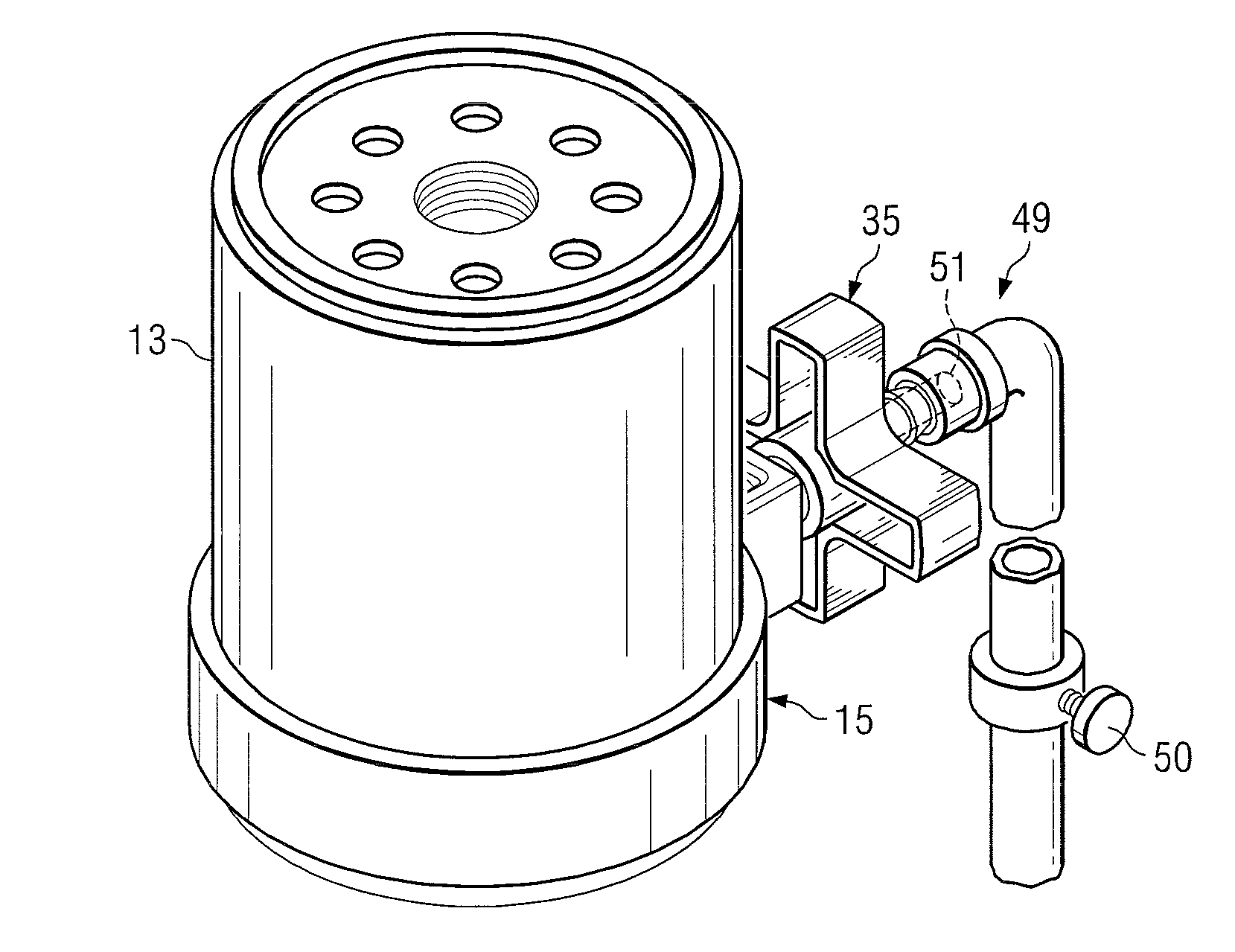
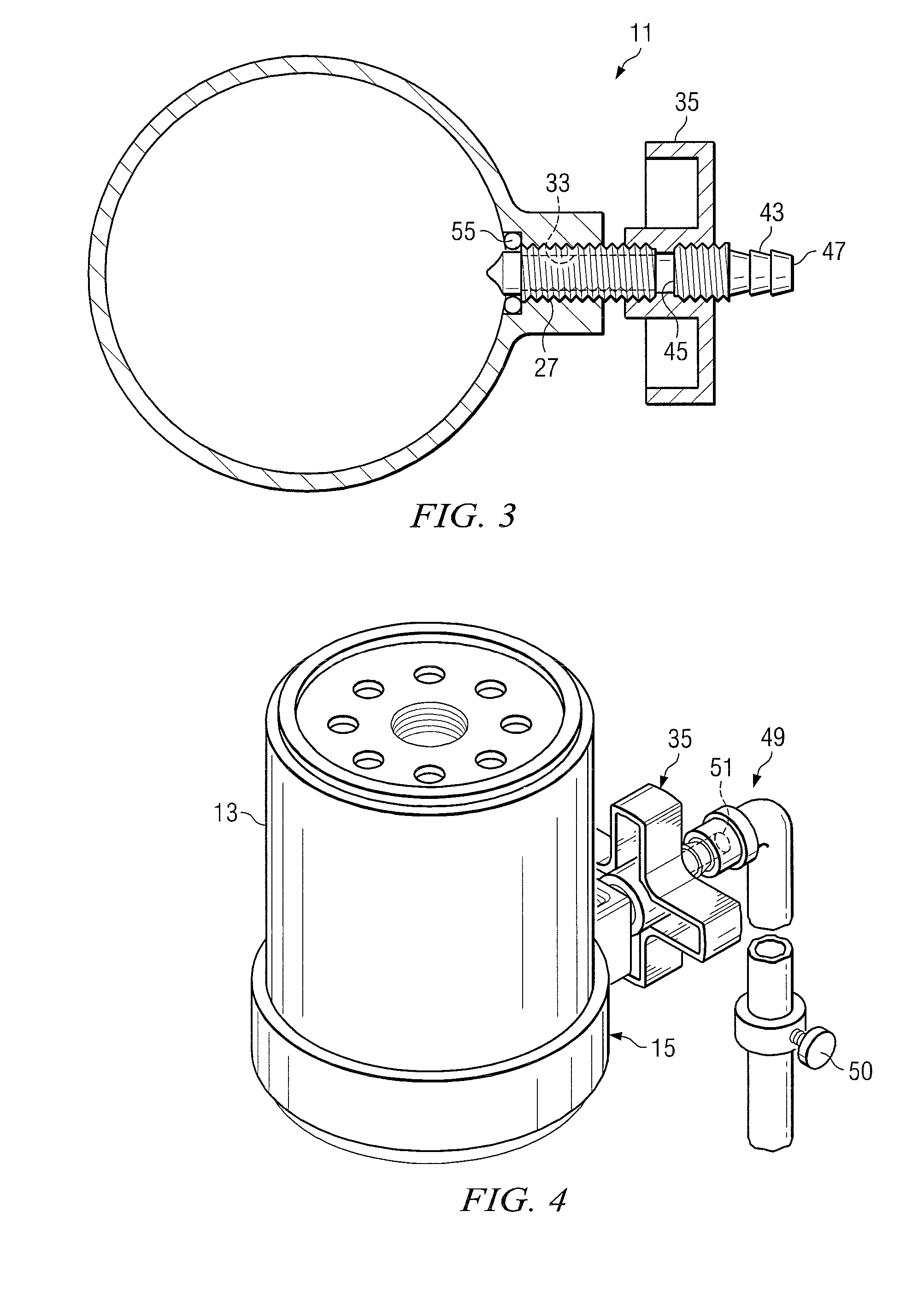
[0021]Turning first to FIG. 4, there is shown a perspective view of the device of the invention 11 which is used for drawing fluid from a container 13. The...


PUM

PropertyMeasurementUnit
circumferential areaaaaaaaaaaa
thicknessaaaaaaaaaa
suctionaaaaaaaaaa

Abstract

A fluid filter draining device is shown for draining fluid from a fluid container, such as an oil filter, in a controlled manner. An engagement ring is frictionally engaged on the outer sidewalls of a fluid filter. The engagement ring carries a threaded screw with a sharpened tip and a channel communicating between an opening at a forward end of the screw and a rear region of the threaded screw. When the screw is turned it penetrates the sidewall of the fluid container and enters the fluid containing cavity of the filter. Fluid is drained through the channel in the drill tip and out through an associated swivel hose connection and swivel hose to a collection container.

Description

CROSS-REFERENCE TO RELATED APPLICATION[0001]The present application claims priority from earlier filed provisional application Ser. No. 61 / 102,399, filed Oct. 3, 2008, entitled “Oil Filter Drain Tool,” by the same inventor.BACKGROUND OF THE INVENTION[0002]1. Field of the Invention[0003]This invention relates generally to an apparatus for removing fluid from a container and more specifically to a device and method for draining hot fluid from, for example, an oil filter before the filter is removed from an associated motor or machinery, to avoid leakage or spillage of the fluid from the filter.[0004]2. Description of the Prior Art[0005]Lubrication systems in machinery, aircraft and vehicles include oil filters, which must be replaced periodically to maintain the good working order of the engine and machinery. For passenger automobiles, many mechanics recommend a oil and filter change every 3,000 miles of travel to maintain maximum engine life. Professional truckers put hundreds of tho...

Claims


Application Information

Patent Timeline
23 Aug 2011
Publication
US8002002B2
IPC
B65B1/04
CPC
B01D35/30; B01D35/31; Y10T137/6123
Inventors
KNOLL, BOBBY