Provider edge-controlled redundancy using pseudo link aggregation control protocol

a pseudo link and control protocol technology, applied in the field of improving reliability in network communications, can solve problems such as switching to the backup link

Active Publication Date: 2011-08-23
CISCO TECH INC
View PDF6 Cites 7 Cited by
  • Summary
  • Abstract
  • Description
  • Claims
  • Application Information

AI Technical Summary

Problems solved by technology

For example, a customer device (e.g., CE or DSLAM on the access side) typically configures one of its uplink ports as primary while the other is configured as backup so that failure of the primary causes a switchover to the backup link.

Method used


Image

  • Provider edge-controlled redundancy using pseudo link aggregation control protocol
  • Provider edge-controlled redundancy using pseudo link aggregation control protocol
  • Provider edge-controlled redundancy using pseudo link aggregation control protocol

Examples


Embodiment Construction

[0011]The following detailed description includes the best currently contemplated modes of carrying out the invention. The description is not to be taken in a limiting sense, but is made merely for the purpose of illustrating the general principles of the invention, since the scope of the invention is best defined by the appended claims. Various inventive features are described below that can each be used independently of one another or in combination with other features.

Overview

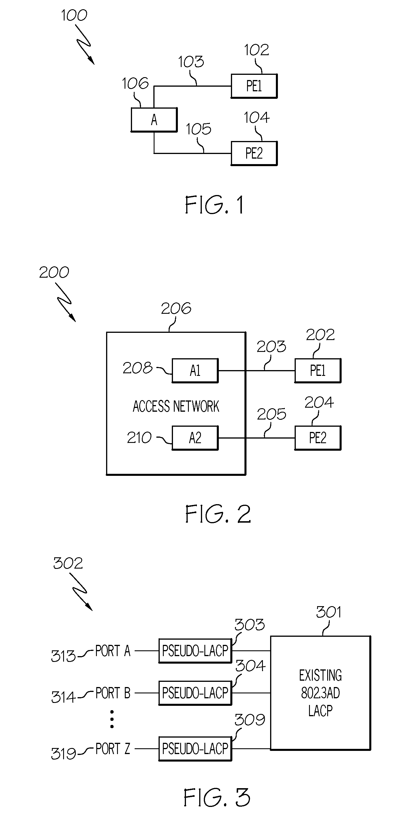
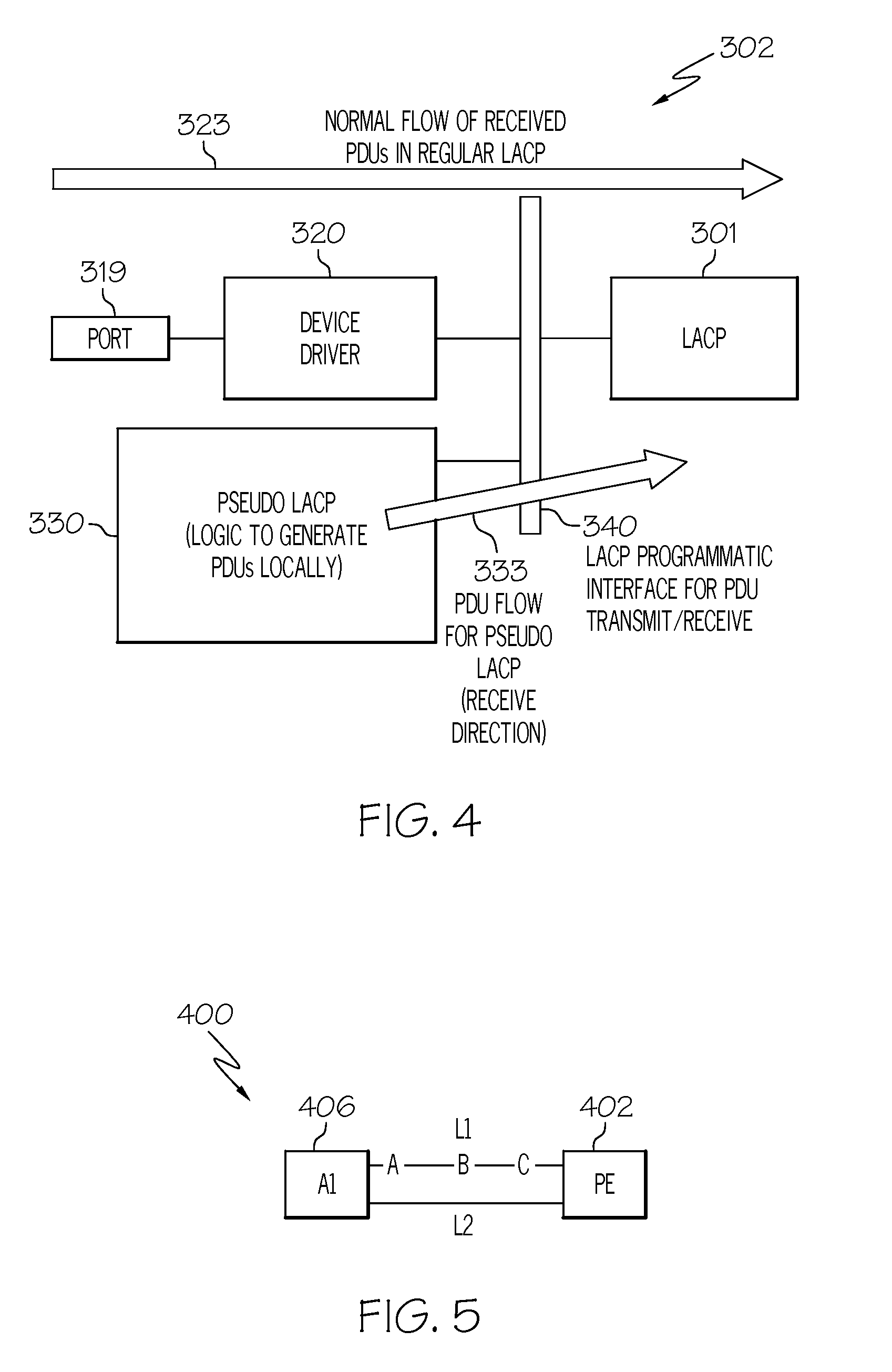
[0012]In one embodiment, a provider edge (PE) device comprises at least one port; and a pseudo-link aggregation control protocol (pseudo-LACP) module instantiated for the at least one the port, wherein the pseudo-LACP module enables dual-homing of an access side of a communication network without running any redundancy protocol between the PE device and the access side.

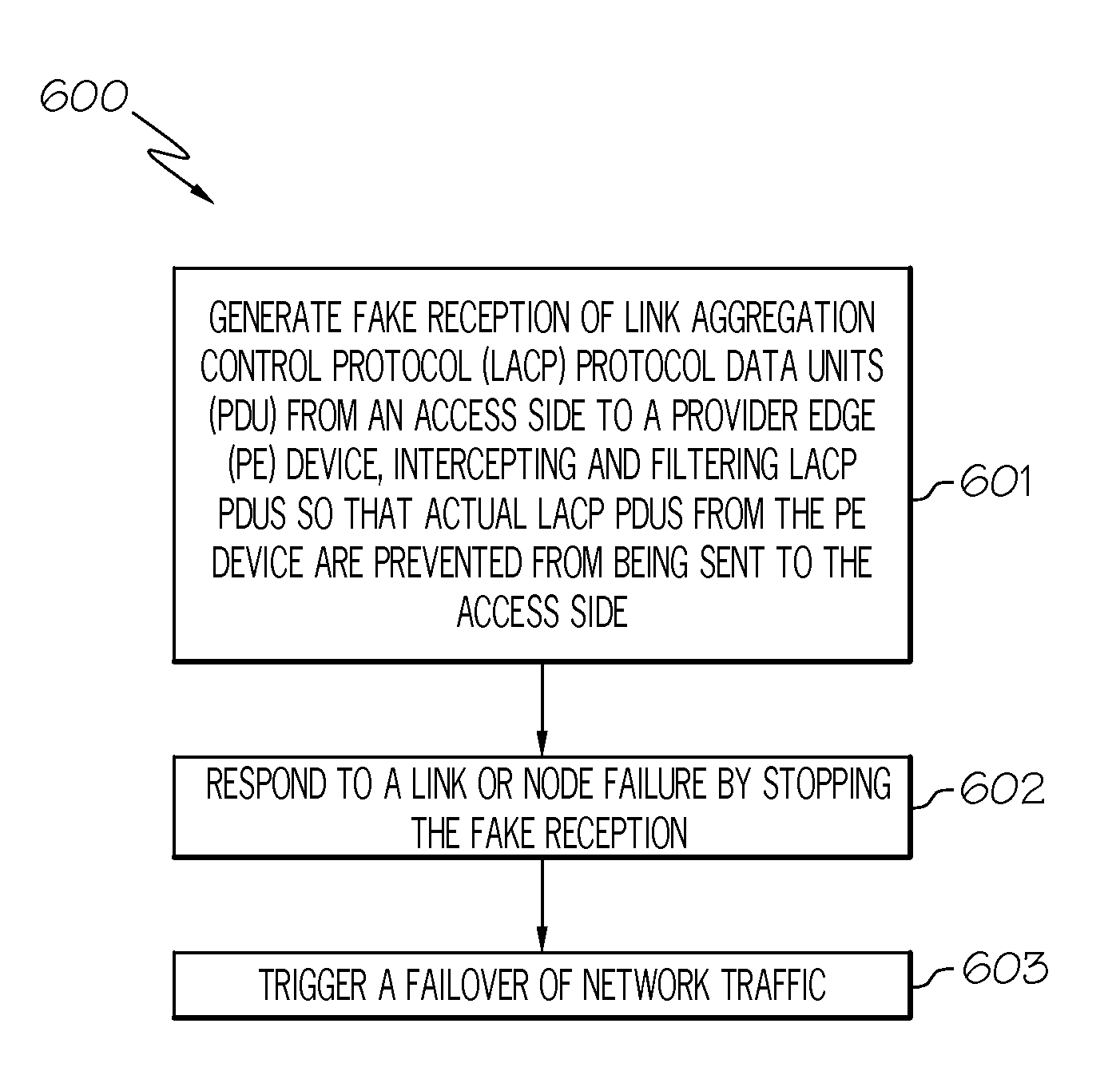
[0013]In another embodiment a method of redundancy on an access side of a communication network comprises faking reception of link aggregatio...


PUM


Abstract

In one embodiment, a system comprises a plurality of provider edge (PE) devices, the PE devices having a plurality of ports; and a pseudo-link aggregation control protocol (LACP) module instantiated for each of the ports. The pseudo-LACP module allows the PE devices to support dual-homing of an access side, the access side including either an access node or an access network, without running any control protocol for redundancy on the access side.

Description

TECHNICAL FIELD[0001]The present disclosure relates generally to improving reliability in network communications by providing link and node redundancy.BACKGROUND OF THE INVENTION[0002]In carrier Ethernet networks, it is required to provide link and node redundancy for certain network topologies including, for example: 1) a dual-homed access node linked to two provider edge (PE) devices—such as a customer edge (CE) or a digital subscriber line access multiplexer (DSLAM) linked to two PE devices—and 2) an access network linked to two provider edge (PE) devices. The two PE devices typically may feed into an aggregation or core network.[0003]There are a number of existing mechanisms available to achieve redundancy for the above topologies. These require, however, the access (e.g., typically a customer of the provider) node or nodes to be running some type of specialized protocol. For example, a customer device (e.g., CE or DSLAM on the access side) typically configures one of its uplink...

Claims


Application Information

Patent Timeline
Patent Type & Authority Patents(United States)
IPC IPC(8): H04J3/16
CPCG06F11/2007H04L12/2859H04L69/40
Inventor SAJASSI, ALISALAM, SAMER
Owner CISCO TECH INC
Why Eureka
Try Eureka