Aerosol therapy device

Inactive Publication Date: 2011-08-30
PARI SPEZIALISTEN FUR EFFEKTIVE INHALATION
View PDF34 Cites 50 Cited by
  • Summary
  • Abstract
  • Description
  • Claims
  • Application Information

AI Technical Summary

Benefits of technology

[0010]Furthermore, a device configuration according to the invention is also characterised in that illnesses such as chronic or allergic sinusitis, inflammations or other infections or conditions (“atrophic rh

Problems solved by technology

Experimental tests on different models of the human nose have demonstrated that when known aerosol therapy devices are used, deposition in the paranasal sinuses is less than expected and desired.
Howev

Method used


Image

  • Aerosol therapy device
  • Aerosol therapy device
  • Aerosol therapy device

Examples


Example

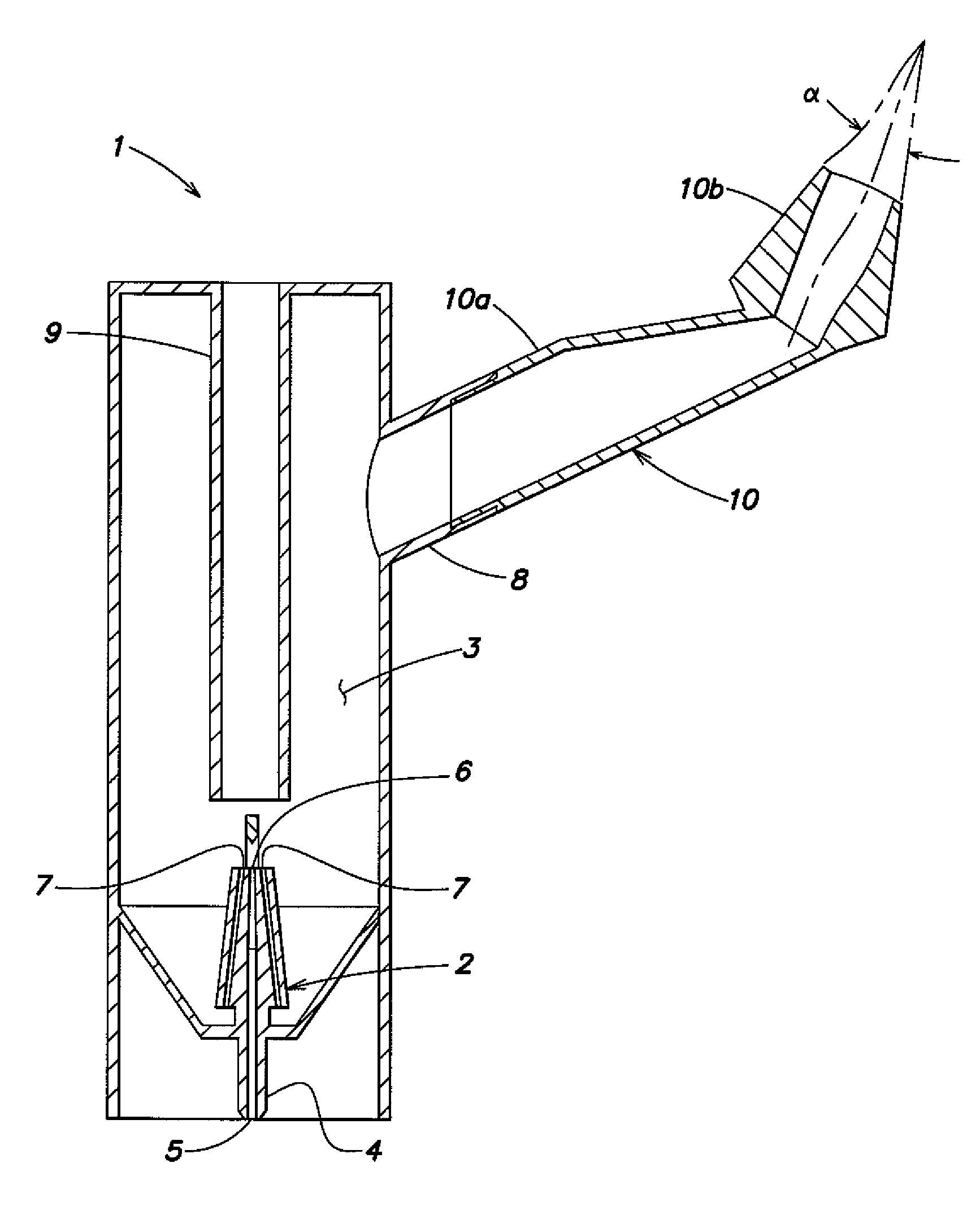
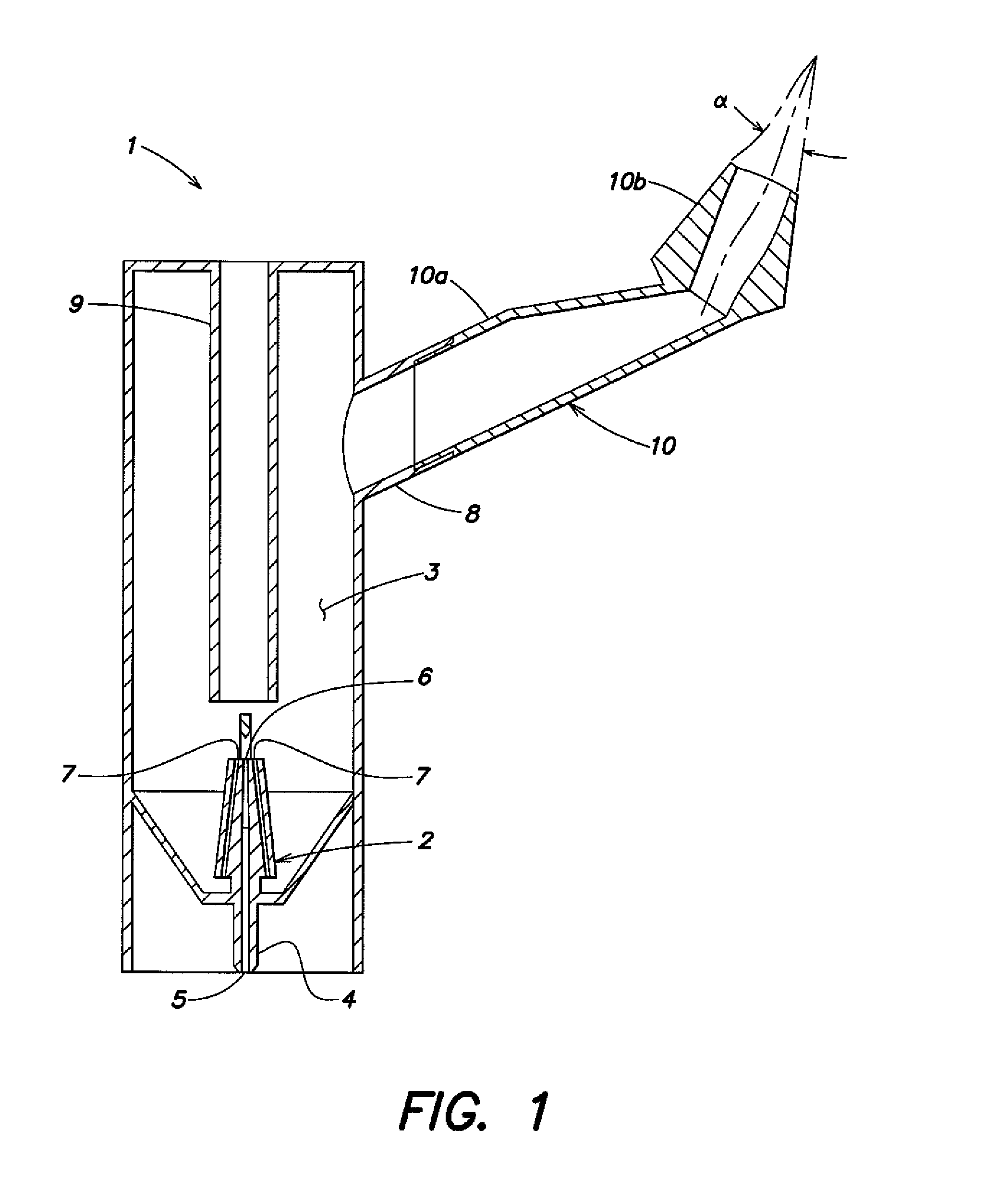
[0021]FIG. 1 shows a first example of a nebulizing device which can be used, within the scope of the invention, for an aerosol therapy as described above. The nebulizing device 1 comprises an aerosol generator 2 arranged in a nebulizing chamber 3. A liquid stored at the bottom of the aerosol generator is nebulized by means of the aerosol generator 2 when compressed air is supplied to the aerosol generator 2 via a connector 4 arranged at one end (at the bottom of FIG. 1) of the aerosol generator. The compressed air flows through a compressed air channel 5 arranged centrally in the aerosol generator and emerges at the other end of the aerosol generator through a nozzle opening 6. The liquid is drawn in through suction channels 7, which are arranged next to the compressed air channel and extend in the aerosol generator from the level of the nozzle opening to the bottom of the aerosol generator and open up towards the liquid stored there, and is nebulized into the nebulizing chamber 3 i...


PUM


Abstract

The invention regards a therapeutic aerosol device in which a main aerosol flow, which is generated with the help of a compressed gas and is supplied to one of the nostrils of a user, is superimposed by pressure fluctuations. The superimposition of the pressure fluctuations occurs directly at one of the two nostrils of the user. A flow resistance is provided in the other nostril.

Description

FIELD OF INVENTION[0001]The invention relates to an aerosol therapy device, in which an aerosol generated in a nebulizing device is supplied through a nosepiece to a patient's nasal cavities in the form of a main aerosol flow.BACKGROUND[0002]Known in this context from “Eindringvermögen von Aerosolen in Nebenräume”, H. Kauff, Archiv. klin. exper. Ohren-, Nasen- and Kehlkopfheilk. 190, 95-108 (1968), is that pressure fluctuations and vibrations can cause aerosol to penetrate the paranasal sinuses, through which the main aerosol flow through the nasal cavities does not otherwise actively flow. An example of these realisations is known from EP 0 507 707 A1. According thereto, an aerosol flow is superimposed with pressure fluctuations which are supposed to cause the aerosol particles / droplets in the main aerosol flow to pass through the ostia and enter the paranasal sinuses. In this way, even though the main aerosol flow does not directly flow through the paranasal sinuses, they can be r...

Claims


Application Information

Patent Timeline
IPC IPC(8): A61M15/08A61M16/00A61M15/00A62B18/02
CPCA61M11/02A61M15/08A61M11/001A61M11/005B05B7/0012B05B7/2435
Inventor BOEHM, ANDREASLUBER, MARTINROSENBEIGER, SVEN
Owner PARI SPEZIALISTEN FUR EFFEKTIVE INHALATION
Why Eureka
Try Eureka