Well servicing tool storage system for subsea well intervention

Inactive Publication Date: 2011-08-30
AX S TECH
View PDF35 Cites 17 Cited by
  • Summary
  • Abstract
  • Description
  • Claims
  • Application Information

AI Technical Summary

Benefits of technology

[0032]an electrical connector mechanism disposed within said male mechanism and said collet fingers, said electrical connector mechanism being actuatable to move between a stored position after the collet fingers are engaged in said receptacle and a connect

Problems solved by technology

Firstly, in the case of PCT/GB2004/000138, it may not be possible to deploy longer rigid tools because of the geometry of getting the tool from the angled pocket into the well centre-line where it has to be made up in the vertical plane, while a portion of the tool remains in the angled pocket.
In

Method used


Image

  • Well servicing tool storage system for subsea well intervention
  • Well servicing tool storage system for subsea well intervention
  • Well servicing tool storage system for subsea well intervention

Examples


Embodiment Construction

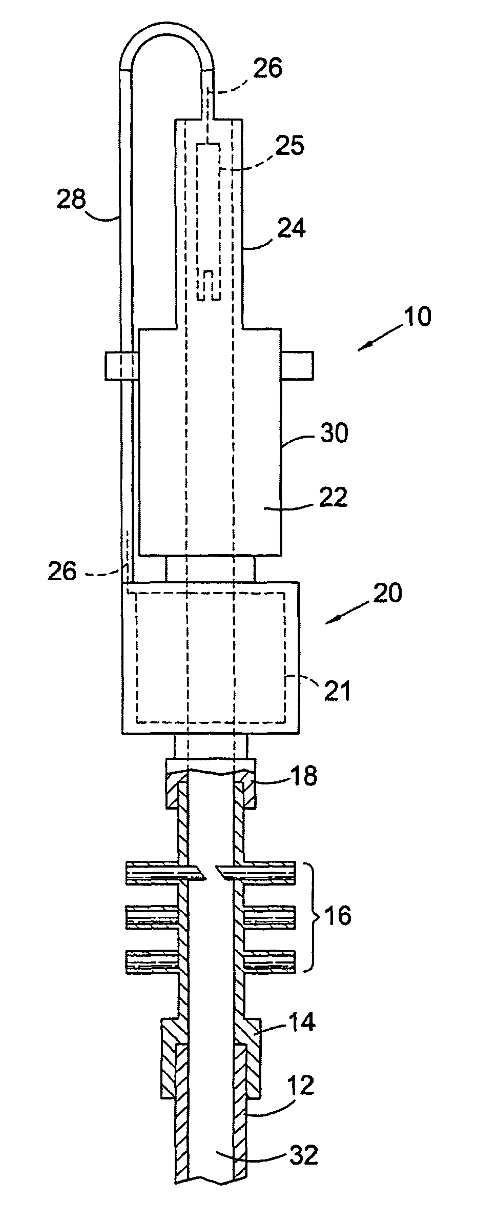
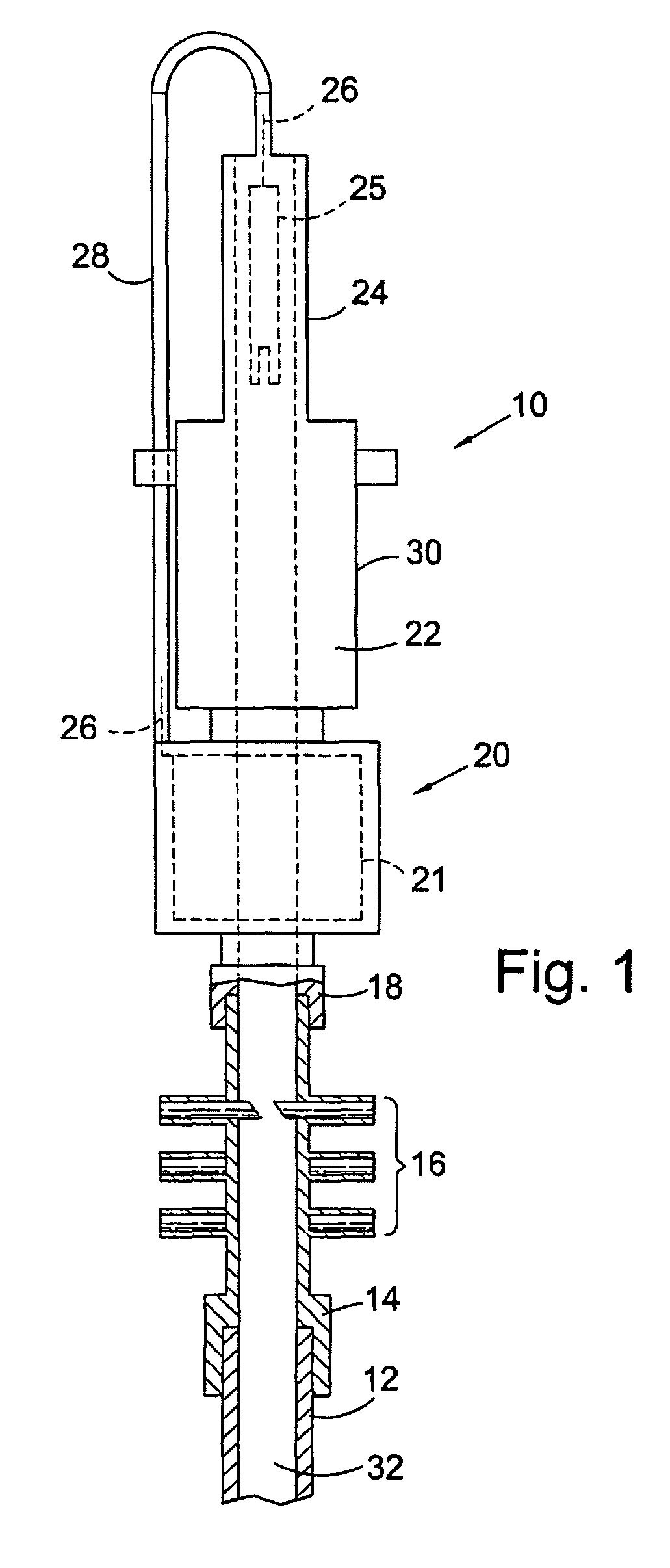
[0043]Reference is first made to FIG. 1 of the drawings which depicts a typical autonomous subsea well intervention system in accordance with an embodiment of the present invention, and generally indicated by reference numeral 10. The system is shown installed on top of a subsea Christmas tree 12. The principal components of the intervention system are: a main system connector 14 which interfaces with the Christmas tree 12, a Blow-Out Preventer 16 (BOP) or flow control valves to affect closure of well and isolation from the environment in an emergency, or in the event having to remove the upper package from the intervention system; an intermediate connector 18 coupled to the top of the BOP connector; a housing 20 containing a coaxial wireline winch 21 (shown in broken outline) coupled to the top of the intermediate connector 4, and disposed axially around the wellbore; a tool storage system 22 as will be later described in detail, and a lubricator or riser section 24 containing a co...


PUM


Abstract

A well servicing tool storage system for subsea well intervention is disclosed which provides a tool storage means as part of the intervention system and which has a plurality of tool storage arms deployed around the tool storage means. Each arm has a clamp capable of clamping a tool, and moving the clamped tool between a stored position near the perimeter of the tool storage means, and a deployed position in the centre of the tool storage means where the tool can be made up into a wireline connection.

Description

FIELD OF THE INVENTION[0001]The present invention relates to subsea well intervention systems, and particularly, but not exclusively, to an improved well servicing tool storage system with subsea well intervention systems.BACKGROUND OF THE INVENTION[0002]The applicant's co-pending International application PCT / GB2004 / 000138 discloses a system for the storage and deployment of wireline conveyed well intervention tooling using a subsea intervention device. The number of such tool storage systems have been disclosed such as in the applicant's above-mentioned PCT application, or in PCT application number PCT / US01 / 23518, but neither are optimized for storing and deploying wireline, or coil tubing in the case of PCT / US01 / 23518 tools using an autonomous, remote system. The aforementioned systems have some disadvantages. Firstly, in the case of PCT / GB2004 / 000138, it may not be possible to deploy longer rigid tools because of the geometry of getting the tool from the angled pocket into the w...

Claims


Application Information

Patent Timeline
IPC IPC(8): E21B23/00E21B17/02E21B19/14E21B33/076H01R13/533H01R13/627
CPCE21B7/124E21B17/023E21B17/028E21B19/146E21B33/076H01R13/6277H01R13/533
Inventor RICHARDS, ANDREWDAVIES, MARK
Owner AX S TECH
Why Eureka
Try Eureka