Loading dock wheel restraint comprising a flexible elongate member

a wheel restraint and flexible technology, applied in the field of vehicle restraints, can solve the problems of wheel chocks often falling out of the position of driveways that are slippery, becoming very difficult to remove, and prone to falling o

Active Publication Date: 2011-08-30
RITE HITE HLDG CORP
View PDF162 Cites 18 Cited by
  • Summary
  • Abstract
  • Description
  • Claims
  • Application Information

AI Technical Summary

Benefits of technology

[0015]In some embodiments, a wheel restraint includes a floor-mounted guide that avoids interference between a flexible elongate member and parts of a vehicle.

Problems solved by technology

However, not all trucks have an ICC bar that can be readily engaged by an ICC-style restraint, so in those cases a wheel restraint can be used for blocking one or more of the truck's wheels.
However, wheel chocks often slip out of position on driveways that are slippery due to oil, rain, ice, sand, gravel or dirt.
Sometimes, wheel chocks wedge so tightly under the wheel that they become very difficult to remove.
Wheel chocks are often loose items that are not permanently attached to the loading dock area, so they tend to get misplaced.
However, such wheel restraints cannot always be readily installed at loading docks that may already have a drain or some other driveway irregularity situated where the track is to be installed.
However, there are some significant problems with the device.
If part of the truck / trailer happens to be at this location, that part could obstruct the movement of the chock.
And the location of the wheels is unpredictable due to the wide variety of trucks and trailers.
Moreover, tools and other equipment are often stowed under the trailer, which could also obstruct the movement of the chock.
Damage may occur to the obstructing part or the wheel restraint itself if the lead screw continues to drive the chock regardless of any obstruction.
Overtime, the dragging motion could eventually erode the surface of the driveway.
However, the device's ability to accommodate wheels of various diameters appears to be quite limited, as the distance between bar and chock plate is fixed.
Increasing the distance between the bar and chock plate to match larger diameter wheels could create an interference problem between the chock plate and a forward set of wheels of a tandem axle trailer.
The interference problem is worsened by the way the chock plate is first extended between the wheels and subsequently moved back against a front portion of the rear wheel.
The greatest space is at the lowest portion of the wheel; however, engaging a wheel at such a low point leads to other problems.
In addition to the specific problems of various powered wheel restraints, such wheel restraints in general are quite elaborate and expensive mechanisms.

Method used


Image

  • Loading dock wheel restraint comprising a flexible elongate member
  • Loading dock wheel restraint comprising a flexible elongate member
  • Loading dock wheel restraint comprising a flexible elongate member

Examples


Embodiment Construction

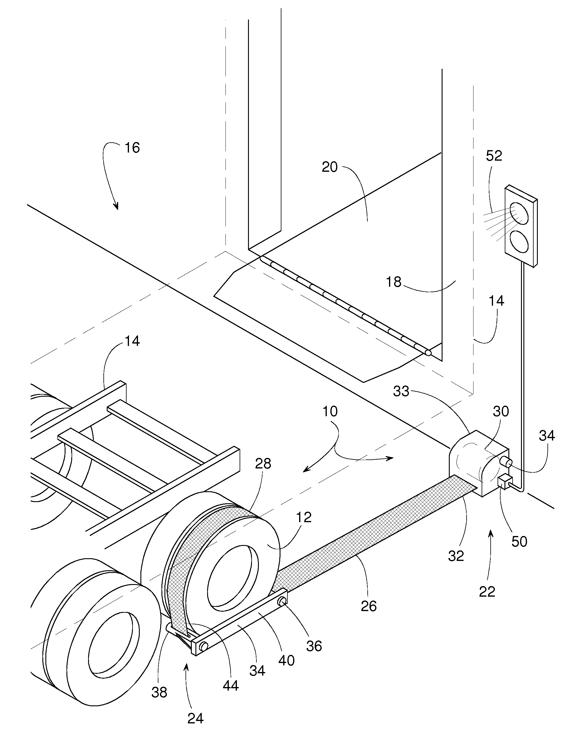
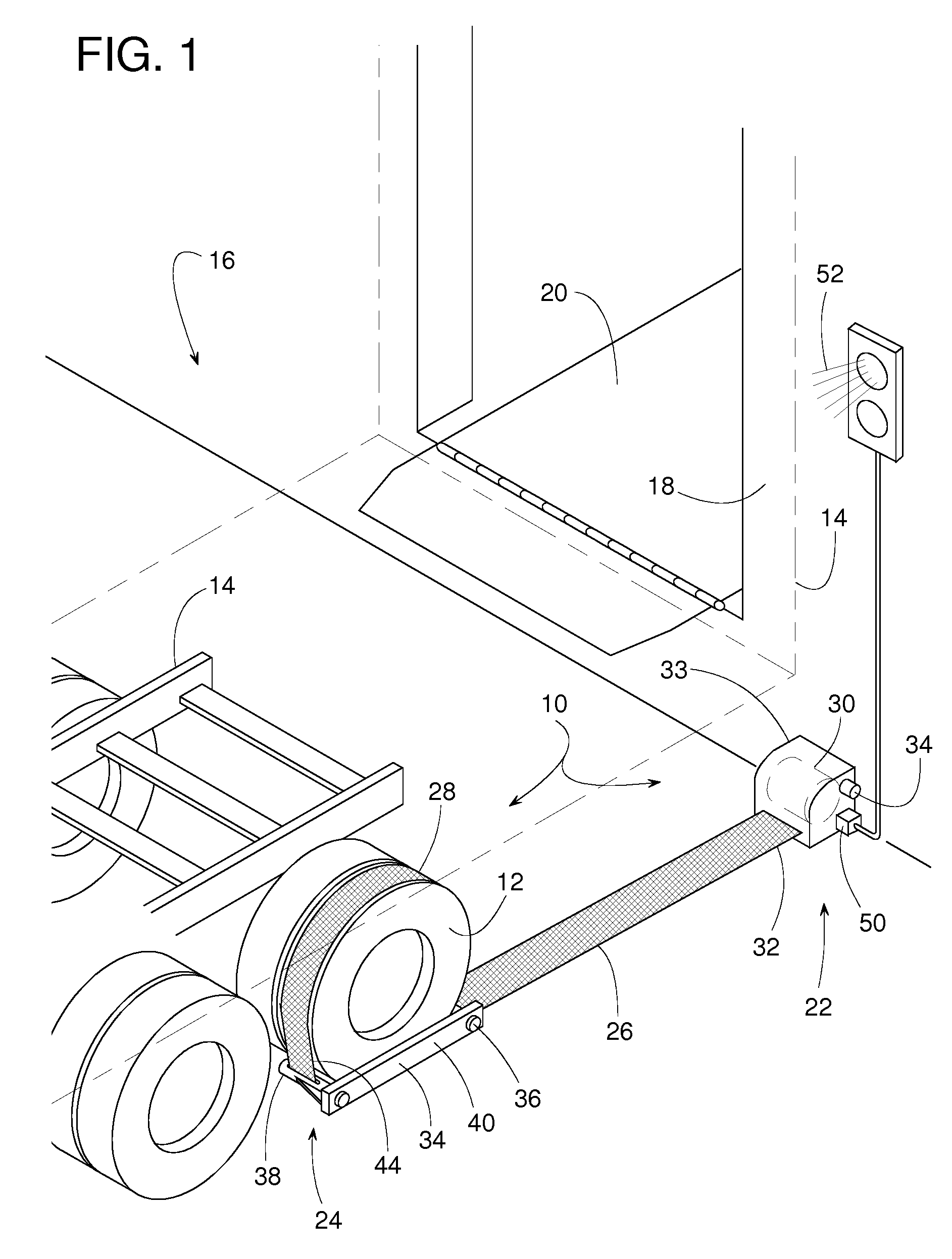
[0021]FIGS. 1 and 2 show a wheel restraint 10 for restraining at least one wheel 12 of a vehicle 14 at a loading dock 16. Restraint 10 is shown in a holding position in FIG. 1 and is shown in a release position in FIG. 2. In the holding position, restraint 10 helps hold vehicle 14 adjacent to a dock face 18 so that cargo can be safely conveyed on and off of vehicle 14. In some cases, a conventional dock leveler 20 can be used to facilitate the loading and unloading operations. An upper section of vehicle 14 is shown in phantom lines to more clearly show restraint 10 in the holding position.

[0022]Restraint 10 basically comprises an anchor 22 that can be installed at a generally fixed location, a barrier 24 that can be manually positioned to selectively engage or release wheel 12, and a flexible elongate member 26 that couples barrier 24 to anchor 22. Although the actual structure of restraint 10 may vary, in some embodiments, elongate member 26 is a nylon strap with a distal section ...


PUM


Abstract

A wheel restraint for restraining a vehicle at a loading dock includes a flexible elongate member with one end that can be manually wrapped at least partially around at least one of the vehicle's wheels. The other end of the elongate member is connected to an anchor that is generally fixed relative to the dock. The anchor preferably includes a reel for taking up slack in the elongate member. When the restraint is not in use, the reel can take up and store the elongate member. The restraint preferably provides a signal that indicates whether the wheel is actually restrained. The restraint might also include a wheel chock coupled to the elongate member. A floor-mounted guide can help prevent interference between the elongate member and certain parts of the vehicle.

Description

FIELD OF THE DISCLOSURE[0001]The subject disclosure generally pertains to restraining a vehicle at a loading dock and more specifically to a wheel restraint.BACKGROUND OF RELATED ART[0002]When a truck, trailer or some other vehicle is parked at a loading dock, often some sort of vehicle restraint is used to keep the truck from inadvertently moving away from an elevated platform of the dock. This allows a forklift truck to safely drive between the dock platform and the truck for the purpose of loading or unloading the cargo inside the truck.[0003]There are a variety of vehicle restraints available that can be installed at a loading dock for engaging the truck's RIG (Rear Impact Guard), also known as an ICC bar. An ICC bar is a beam that extends horizontally across the rear of a truck, just below the truck bed. Its primary purpose is to prevent an automobile from under-riding the truck in a rear-end collision. However, not all trucks have an ICC bar that can be readily engaged by an I...

Claims


Application Information

Patent Timeline
Patent Type & Authority Patents(United States)
IPC IPC(8): B61H13/00
CPCB65G69/005
Inventor ANDERSEN, JONATHANCOTTON, TIMOTHYLESSARD, KURTWIEBERDINK, BENJAMIN
Owner RITE HITE HLDG CORP
Why Eureka
Try Eureka