
Shielded integrated connector module

Active Publication Date: 2011-08-30
TYCO ELECTRONICS LOGISTICS AG (CH)
View PDF6 Cites 24 Cited by
  • Summary
  • Abstract
  • Description
  • Claims
  • Application Information

AI Technical Summary

Benefits of technology

[0005]In one embodiment, an electrical connector assembly is provided for mating with electrical plugs. The electrical connector assembly includes a housing having a top wall and a bottom wall that is opposite the top wall. The housing includes a mating face having ports that are configured to receive the electrical plugs therein. A jack sub-assembly is held by the housing. The jack sub-assembly includes jacks having electrical contacts held within the ports for engagement with the electrical plugs. The jack sub-assembly includes a signal pin array having signal pins for connection to a host circuit board. The signal pin array includes a front side extending along the bottom wall of the housing. An electrically conductive outer shield covers the top wall of the housing. The outer shield includes a bottom flap covering an end of the bottom wall of the housing. An electrically conductive bottom shield covers the bottom wall of the housing between the bottom f

Problems solved by technology

However, computer connections may generate or be susceptible to noise due to the high frequency signals which are transmitted along the communication lines between the computer and other devices.
Because of the noise that may be present or generated at the interface between the modular plug and the modular jack, there may be a failure to meet system electromagnetic interference (EMI) performance requirements.
Furthermore, noise may also result in system current injection (CI) failures.
However, as the density of electrical connections to the host circuit board and the speed of the signals increases, the signal pins may experience cross talk and / or receive EMI from neighboring connections on the host circuit board.

Method used


Image

  • Shielded integrated connector module
  • Shielded integrated connector module
  • Shielded integrated connector module

Examples


Embodiment Construction

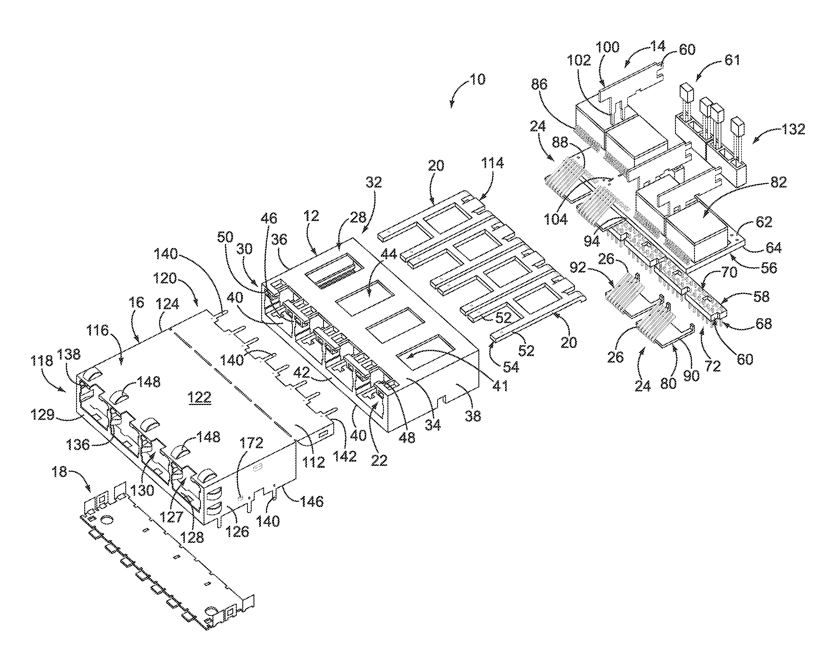
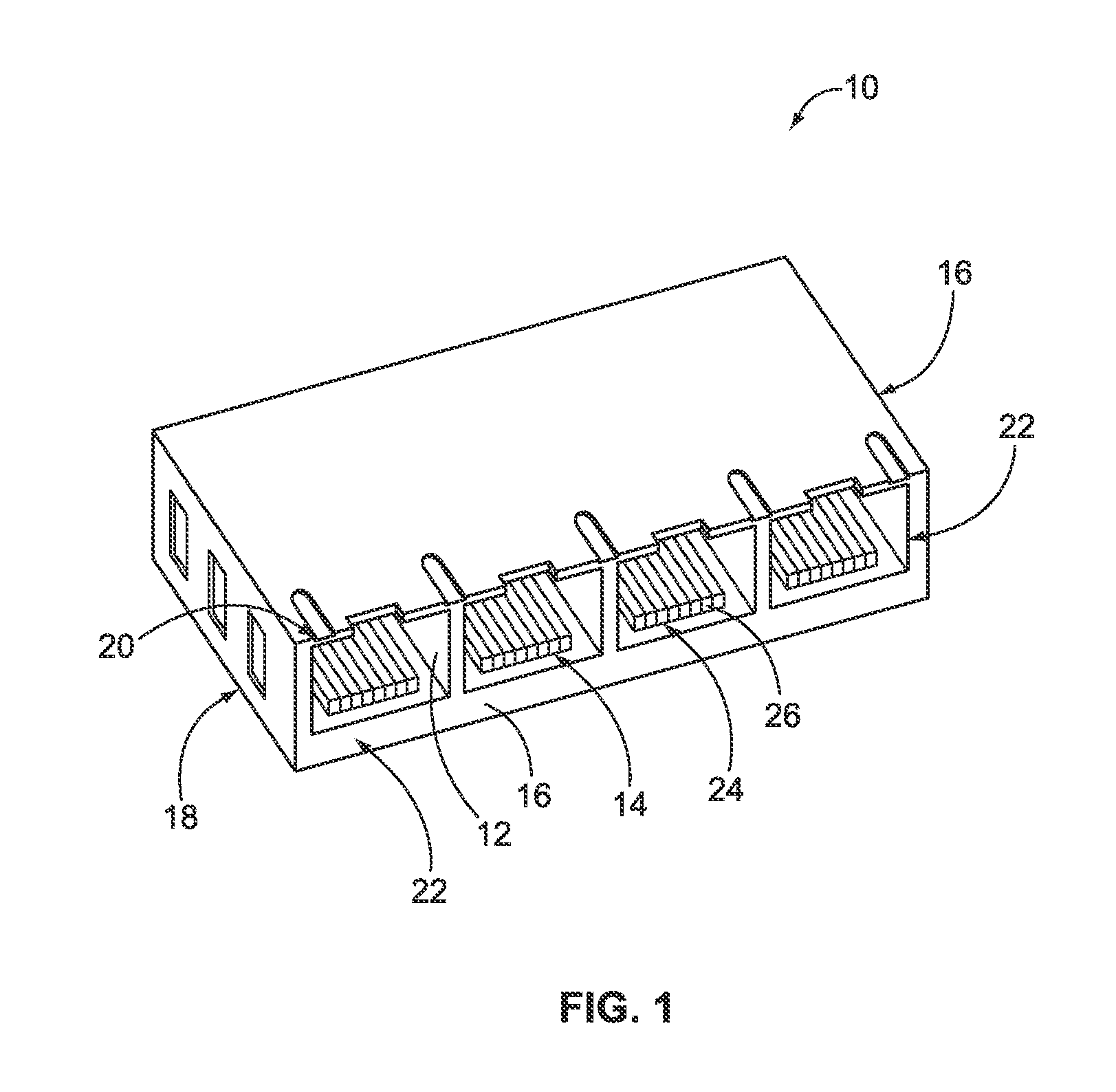
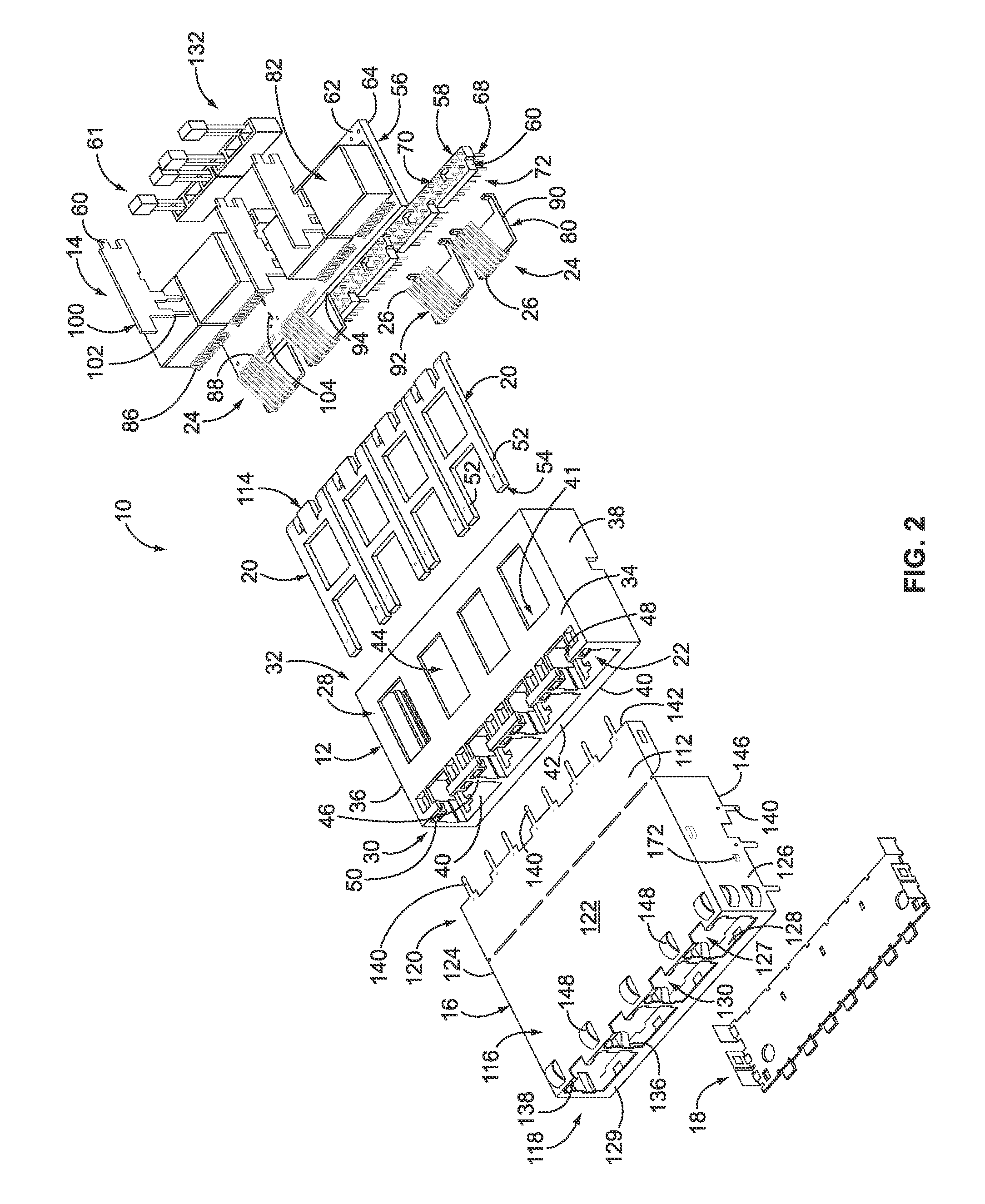
[0015]FIG. 1 is a top perspective view of an exemplary embodiment of a shielded integrated connector module (ICM) 10. FIG. 2 is an exploded perspective view of the ICM 10. The ICM 10 includes a dielectric housing 12, a jack sub-assembly 14 held by the housing 12, and an electrically conductive outer shield 16 surrounding a portion of the housing 12. The ICM 10 also includes an electrically conductive bottom shield 18 and a plurality of optional light pipe members 20. The housing 12 includes a plurality of ports 22 that each receives a modular plug (not shown) therein. The jack sub-assembly 14 includes a plurality of modular jacks 24 that each includes an array of electrical contacts 26. The jack sub-assembly 14 is held by the housing 12 such that the electrical contacts 26 of each modular jack 24 extend within a corresponding one of the ports 22 for engagement with corresponding electrical contacts (not shown) of the modular plug. In the exemplary embodiment, the ICM 10 is configure...


PUM


Abstract

An electrical connector assembly is provided for mating with electrical plugs. The electrical connector assembly includes a housing having a top wall and a bottom wall that is opposite the top wall. The housing includes a mating face having ports that are configured to receive the electrical plugs therein. A jack sub-assembly is held by the housing. The jack sub-assembly includes jacks having electrical contacts held within the ports for engagement with the electrical plugs. The jack sub-assembly includes a signal pin array having signal pins for connection to a host circuit board. The signal pin array includes a front side extending along the bottom wall of the housing. An electrically conductive outer shield covers the top wall of the housing. The outer shield includes a bottom flap covering an end of the bottom wall of the housing. An electrically conductive bottom shield covers the bottom wall of the housing between the bottom flap of the outer shield and the front side of the signal pin array.

Description

BACKGROUND OF THE INVENTION[0001]The subject matter described and / or illustrated herein relates generally to electrical connector assemblies, and more particularly, to shielded integrated connector modules (ICMs) that mate with a plurality of modular plugs.[0002]Modular plugs and modular jacks, including ICMs, are widely used to provide electrical connections between devices. For example, modular plugs and modular jacks are sometimes used to connect computer equipment together. However, computer connections may generate or be susceptible to noise due to the high frequency signals which are transmitted along the communication lines between the computer and other devices. Susceptibility to noise is a particular concern in high density applications, such as in communication modules, where numerous ports must be provided for the connection of communication lines between a computer and other devices. For example, commercial network providers to the Internet typically require hundreds of ...

Claims


Application Information

Patent Timeline
IPC IPC(8): H01R9/03
CPCH01R13/6461H01R13/6587H01R24/64
Inventor DUNWOODY, STEVEN DAVIDGILLETTE, CANDACE EILEENSZCZESNY, DAVID STANLEYSHIELDS, LINDA ELLENRANNOW, RANDY K.
Owner TYCO ELECTRONICS LOGISTICS AG (CH)
Learn More