Work vehicle having hydraulic stepless speed changing apparatus

a technology of hydraulic stepless and speed changing apparatus, which is applied in the direction of gearing control, gearing elements, gearing operation, etc., can solve the problems of sudden release of the braking function of the hydrostatic stepless speed changing apparatus, unstable work vehicle, and inability to smoothly carry out the shift operation, so as to achieve smooth speed change operation, maintain resistance against inadvertent movement, and facilitate the effect of construction

Active Publication Date: 2011-08-30
KUBOTA LTD
View PDF5 Cites 4 Cited by
  • Summary
  • Abstract
  • Description
  • Claims
  • Application Information

AI Technical Summary

Benefits of technology

[0006]The object of the present invention is to provide a work vehicle which is reliable and stable while allowing a smooth switchover operation of the gear type auxiliary speed changing apparatus, by adopting an arrangement for preventing sudden release of torque of the hydraulic stepless speed changing apparatus.
[0013]With the above construction, when the brake operating member is operated to the braking side, the brake is rendered into its braking state and at the same time the unload valve is released to guide high-pressure work oil from the high-pressure side circuit to the hydraulic tank via the return oil passage, thus releasing a high-pressure condition. With this, the drive torque being applied to the gear type auxiliary speed changing apparatus is released, so that a speed changing operation may be effected smoothly. Moreover, as the throttle valve functions to restrict sudden transport of the high-pressure work oil guided from the high-pressure side circuit to the hydraulic tank, but the valve allows gradual guidance thereof, there occurs no sudden release of the torque of the stepless hydrostatic speed changing apparatus. With this, as the torque in the stepless hydrostatic speed changing apparatus is maintained at least temporarily, it is possible to maintain resistance against inadvertent movement of the work vehicle. Consequently, by effecting a braking operation which is unavoidably required for a shifting operation on the auxiliary speed changing apparatus, the release of the torque of the hydraulic stepless speed changing apparatus can proceed gradually. Hence, as compared with the conventional construction which requires both a braking operation and a bypass opening operation, the operation of the inventive construction is easer.
[0021]With the above construction, when the manual operating member, more particularly, an auxiliary speed changing member for an auxiliary speed changing apparatus in one preferred embodiment, is operated, the unload valve is released to guide high-pressure work oil from the high-pressure side circuit to the hydraulic tank via the return oil passage, thus releasing a high-pressure condition. With this, the drive torque being applied to the gear type auxiliary speed changing apparatus is released, so that a speed changing operation may be effected smoothly. Moreover, as the throttle valve does not allow sudden transport of the high-pressure work oil guided from the high-pressure side circuit to the hydraulic tank, but allows gradual guidance thereof, there occurs no sudden release of the torque of the stepless hydrostatic speed changing apparatus. With this, as the torque in the stepless hydrostatic speed changing apparatus is maintained at least temporarily, it is possible to maintain resistance against inadvertent movement of the work vehicle. Hence, the release of the torque of the hydraulic stepless speed changing apparatus can be effected in response to an operation on the manual operating member. This allows various workshop designing of the operating system for switching over the unload valve, thus making it easy to simplify the construction for operable coupling with the unload valve.

Problems solved by technology

Therefore, the shifting operation cannot sometimes be effected smoothly.
However, with this conventional art, if bypass between the high-pressure side circuit and the low-pressure side circuit is established by an operation of the operating lever simultaneously with a stepping operation of the brake pedal to the braking side, the torque of the hydrostatic stepless speed changing apparatus is released all at one time, thus resulting in sudden release of the torque of the hydrostatic stepless speed changing apparatus This release of torque results in sudden release of the braking function of the hydrostatic stepless speed changing apparatus.
As a result, the work vehicle becomes unstable until complete application of a braking force on the slope or the like.

Method used


Image

  • Work vehicle having hydraulic stepless speed changing apparatus
  • Work vehicle having hydraulic stepless speed changing apparatus
  • Work vehicle having hydraulic stepless speed changing apparatus

Examples


Embodiment Construction

[General Construction of Work Vehicle]

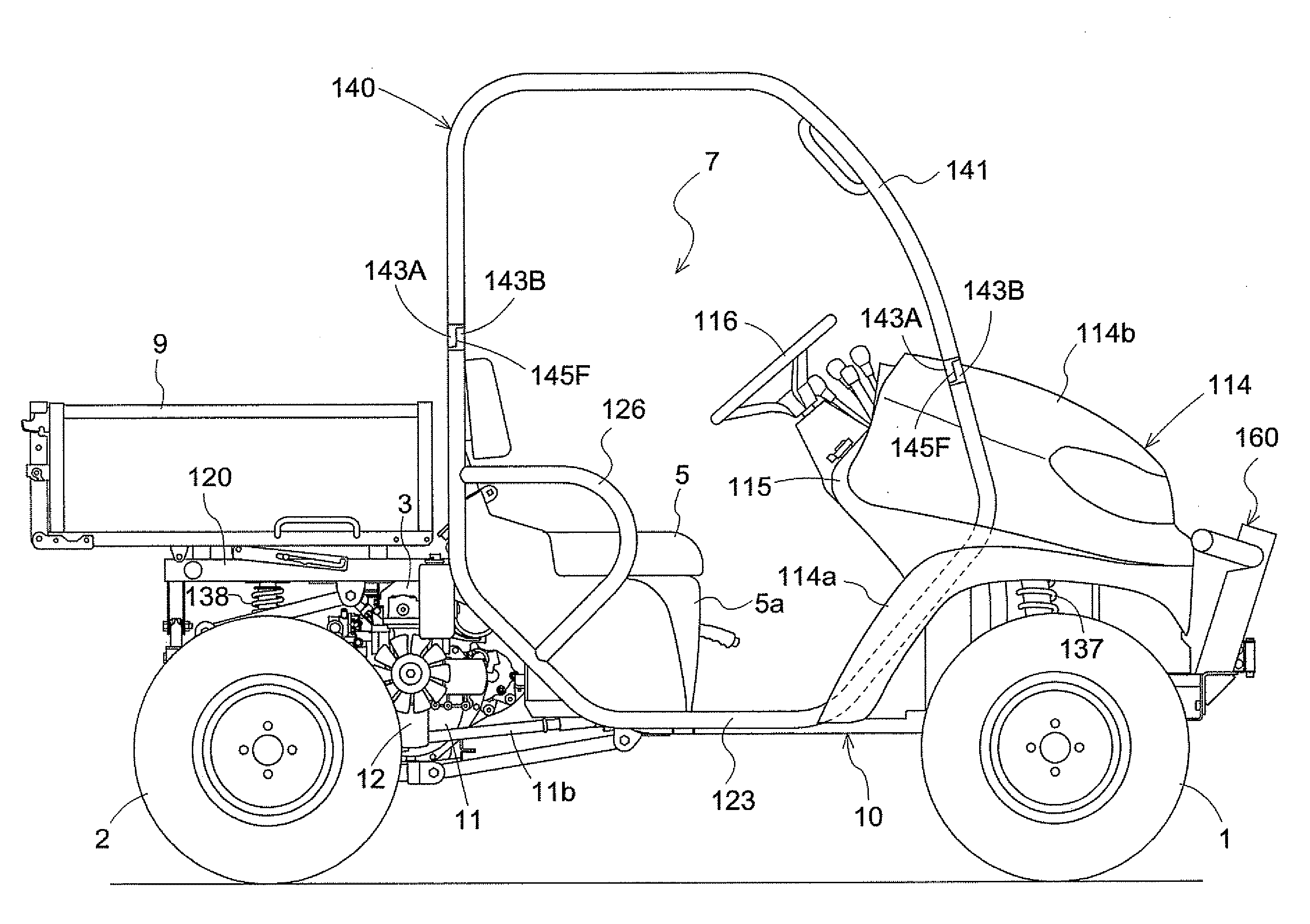
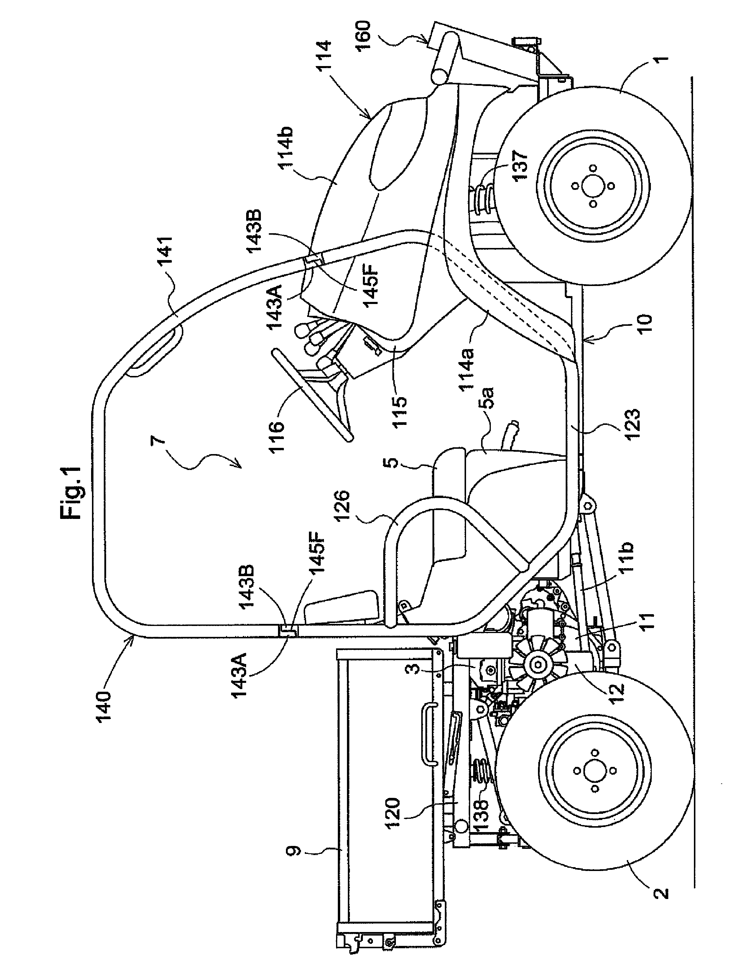
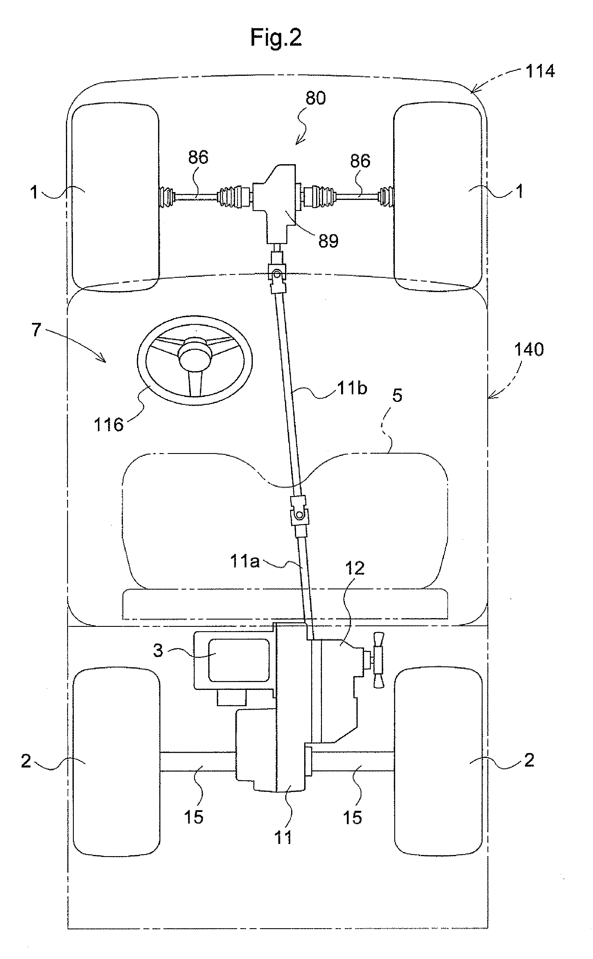
[0051]With reference to FIG. 1 and FIG. 2, there will be explained a general construction of a work vehicle relating to the present invention. FIG. 1 is an overall right side view of the work vehicle. FIG. 2 is an overall plan view for explaining a transmission construction of the work vehicle. As shown in FIG. 1 and FIG. 2, the work vehicle includes steerable right and left front wheels 1 supported to front portions of a vehicle body frame 10, and non-steerable right and left rear wheels 2 supported to rear portions of the vehicle body frame 10. Hence, the vehicle is configured as a four-wheel drive vehicle. At an fore / aft intermediate portion of the work vehicle, there is provided a driving section 7 for two passengers. And, rearwardly of this driving section 7, there is provided a rear load mount section having a loading platform 9 capable of dumping actions.

[0052]A seat supporting panel 5a is mounted in such a manner as to cover an upper por...


PUM


Abstract

A work vehicle includes a hydraulic stepless speed changing apparatus and a gear type speed changing apparatus operable to receive output from the hydraulic stepless speed changing apparatus to convert it into a plurality of stages of speed. A return oil passage connected to a high-pressure side circuit of the hydraulic stepless speed changing apparatus is connected to a hydraulic tank. The return oil passage incorporates an unload valve and a throttle valve, between which an operably coupling mechanism is provided. This operably coupling mechanism switches over the unload valve to an unload condition in response to an operational displacement of a brake operating member for operating a brake to its braking side.

Description

BACKGROUND OF THE INVENTION[0001]1. Field of the Invention[0002]The present invention relates to a work vehicle having a hydraulic stepless speed changing apparatus and a gear type speed changing apparatus.[0003]2. Description of the Related Art[0004]From the Japanese Patent Application “Kokai” No. 2004-257447, there is known, as an example of the above-noted work vehicle, a multi-purpose work vehicle configured such that engine power is inputted to a main speed changing apparatus to be speed-changed in a stepless manner, and the resultant speed-changed power in a predetermined rotational direction is transmitted to a gear type auxiliary speed changing apparatus to be converted selectively into a forward driving power or a reverse driving power in plurality of stages of forward / reverse speeds, respectively. With this work vehicle, when the any speed changing apparatus is to be switched over, the speed changing operation is effected after a traveling brake is activated for braking. H...

Claims


Application Information

Patent Timeline
Patent Type & Authority Patents(United States)
IPC IPC(8): F16H61/40
CPCF16H61/4157F16H61/448F16H61/4017B60Y2200/41F16H47/02F16H59/54Y10T477/621Y10T477/636
Inventor ISHIDA, YUUKISHIMADA, HIROSHINADA, KOJINAKAJI, MASARUBESSHO, HIROKIMURAKAWA, MASATAKENAKATANI, YASUNOBU
Owner KUBOTA LTD
Why Eureka
Try Eureka