Work Vehicle Having Hydraulic Stepless Speed Changing Apparatus

Active Publication Date: 2009-09-24
KUBOTA LTD
View PDF3 Cites 7 Cited by
  • Summary
  • Abstract
  • Description
  • Claims
  • Application Information

AI Technical Summary

Benefits of technology

[0021]With the above construction, when the manual operating member, more particularly, an auxiliary speed changing member for an auxiliary speed changing apparatus in one preferred embodiment, is operated, the unload valve is released to guide high-pressure work oil from the high-pressure side circuit to the hydraulic tank via the return oil passage, thus releasing a high-pressure condition. With this, the drive torque being applied to the gear type auxiliary speed changing apparatus is released, so that a speed changing operation may be effected smoothly. Moreover, as the throttle valve does not allow sudden transport of the high-pressure work oil guided from the high-pressure side circuit to the

Problems solved by technology

Therefore, the shifting operation cannot sometimes be effected smoothly.
However, with this conventional art, if bypass between the high-pressure side circuit and the low-pressure side circuit is established by an operation of the operating lever simultaneously with a stepping operation of the brake pedal to the braking side, the torque of the hydrostatic stepless speed changing a

Method used


Image

  • Work Vehicle Having Hydraulic Stepless Speed Changing Apparatus
  • Work Vehicle Having Hydraulic Stepless Speed Changing Apparatus
  • Work Vehicle Having Hydraulic Stepless Speed Changing Apparatus

Examples


Embodiment Construction

General Construction of Work Vehicle

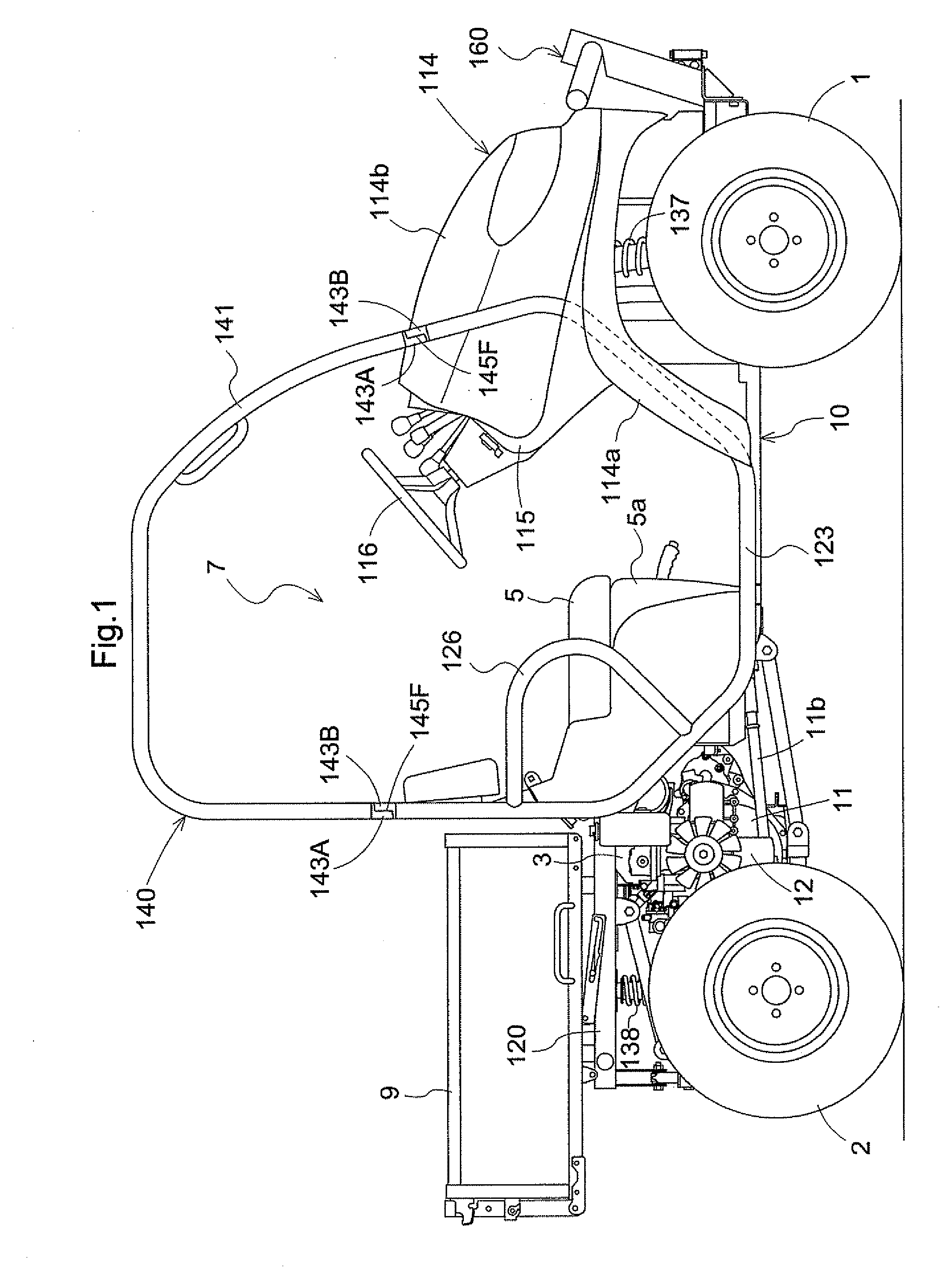
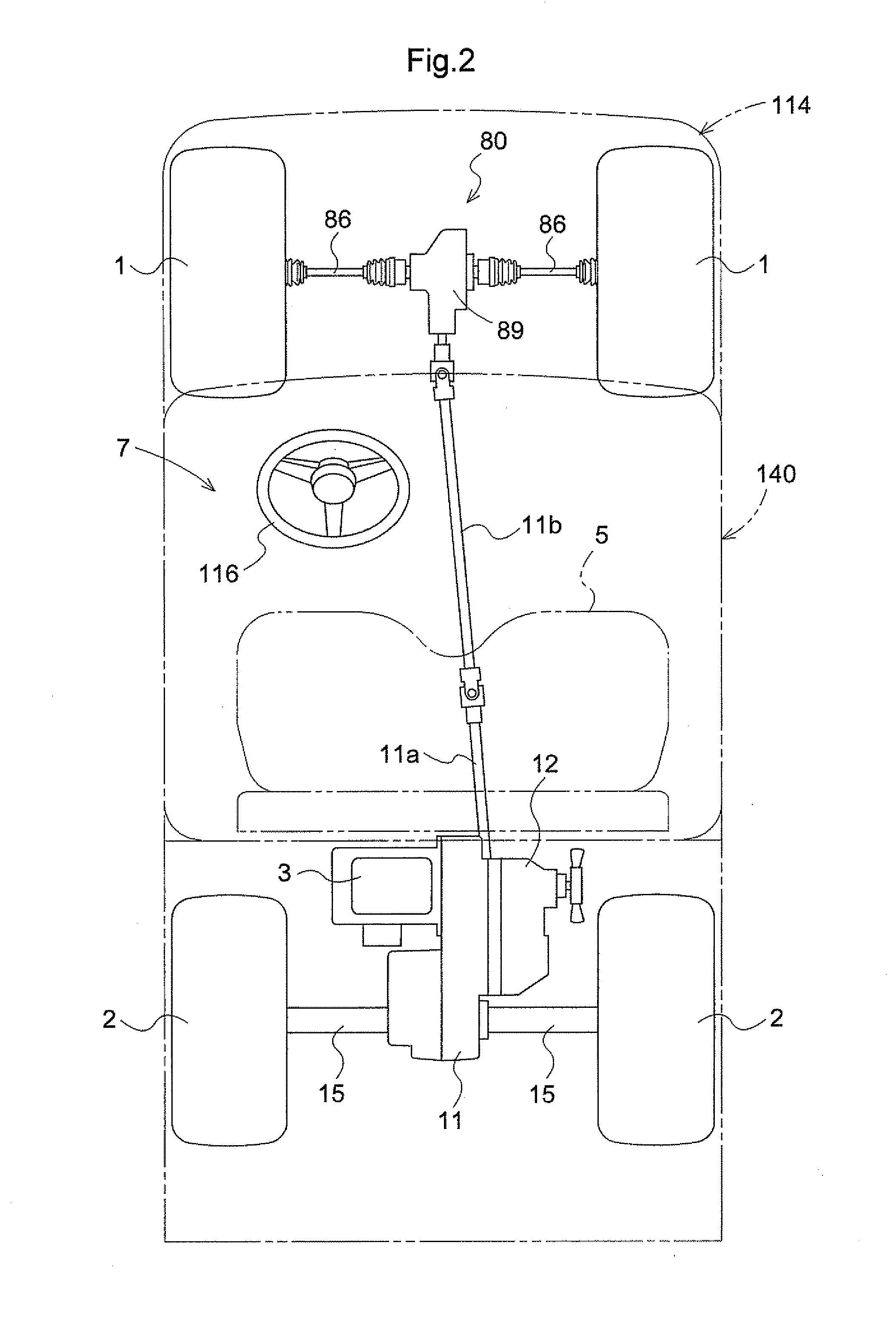
[0051]With reference to FIG. 1 and FIG. 2, there will be explained a general construction of a work vehicle relating to the present invention. FIG. 1 is an overall right side view of the work vehicle. FIG. 2 is an overall plan view for explaining a transmission construction of the work vehicle. As shown in FIG. 1 and FIG. 2, the work vehicle includes steerable right and left front wheels 1 supported to front portions of a vehicle body frame 10, and non-steerable right and left rear wheels 2 supported to rear portions of the vehicle body frame 10. Hence, the vehicle is configured as a four-wheel drive vehicle. At an fore / aft intermediate portion of the work vehicle, there is provided a driving section 7 for two passengers. And, rearwardly of this driving section 7, there is provided a rear load mount section having a loading platform 9 capable of dumping actions.

[0052]A seat supporting panel 5a is mounted in such a manner as to cover an upper porti...


PUM


Abstract

A work vehicle includes a hydraulic stepless speed changing apparatus and a gear type speed changing apparatus operable to receive output from the hydraulic stepless speed changing apparatus to convert it into a plurality of stages of speed. A return oil passage connected to a high-pressure side circuit of the hydraulic stepless speed changing apparatus is connected to a hydraulic tank. The return oil passage incorporates an unload valve and a throttle valve, between which an operably coupling mechanism is provided. This operably coupling mechanism switches over the unload valve to an unload condition in response to an operational displacement of a brake operating member for operating a brake to its braking side.

Description

BACKGROUND OF THE INVENTION[0001]1. Field of the Invention[0002]The present invention relates to a work vehicle having a hydraulic stepless speed changing apparatus and a gear type speed changing apparatus.[0003]2. Description of the Related Art[0004]From the Japanese Patent Application “Kokai” No. 2004-257447, there is known, as an example of the above-noted work vehicle, a multi-purpose work vehicle configured such that engine power is inputted to a main speed changing apparatus to be speed-changed in a stepless manner, and the resultant speed-changed power in a predetermined rotational direction is transmitted to a gear type auxiliary speed changing apparatus to be converted selectively into a forward driving power or a reverse driving power in plurality of stages of forward / reverse speeds, respectively. With this work vehicle, when the any speed changing apparatus is to be switched over, the speed changing operation is effected after a traveling brake is activated for braking. H...

Claims


Application Information

Patent Timeline
IPC IPC(8): B60W10/00B60W30/18
CPCB60Y2200/41F16H47/02F16H59/54Y10T477/621F16H61/4157F16H61/448Y10T477/636F16H61/4017
Inventor ISHIDA, YUUKISHIMADA, HIROSHINADA, KOJINAKAJI, MASARUBESSHO, HIROKIMURAKAWA, MASATAKENAKATANI, YASUNOBU
Owner KUBOTA LTD
Why Eureka
Try Eureka