Quick change adapter for mounting brushes

a technology of adapters and brushes, applied in the direction of couplings, manufacturing tools, rod connections, etc., can solve the problems of affecting the quality of the finished product,

Inactive Publication Date: 2011-09-06
WEILER BRUSH CO INC
View PDF6 Cites 43 Cited by
  • Summary
  • Abstract
  • Description
  • Claims
  • Application Information

AI Technical Summary

Problems solved by technology

However, mounting and removing the replaceable component can be tedious, and time consuming.
As such, the downtime involved in changing tools greatly adds to the cost of the product.
Also, if the tool has been operating for sometime, the worn component may be hot to the touch, making its removal potentially harmful.

Method used


Image

  • Quick change adapter for mounting brushes
  • Quick change adapter for mounting brushes
  • Quick change adapter for mounting brushes

Examples


Embodiment Construction

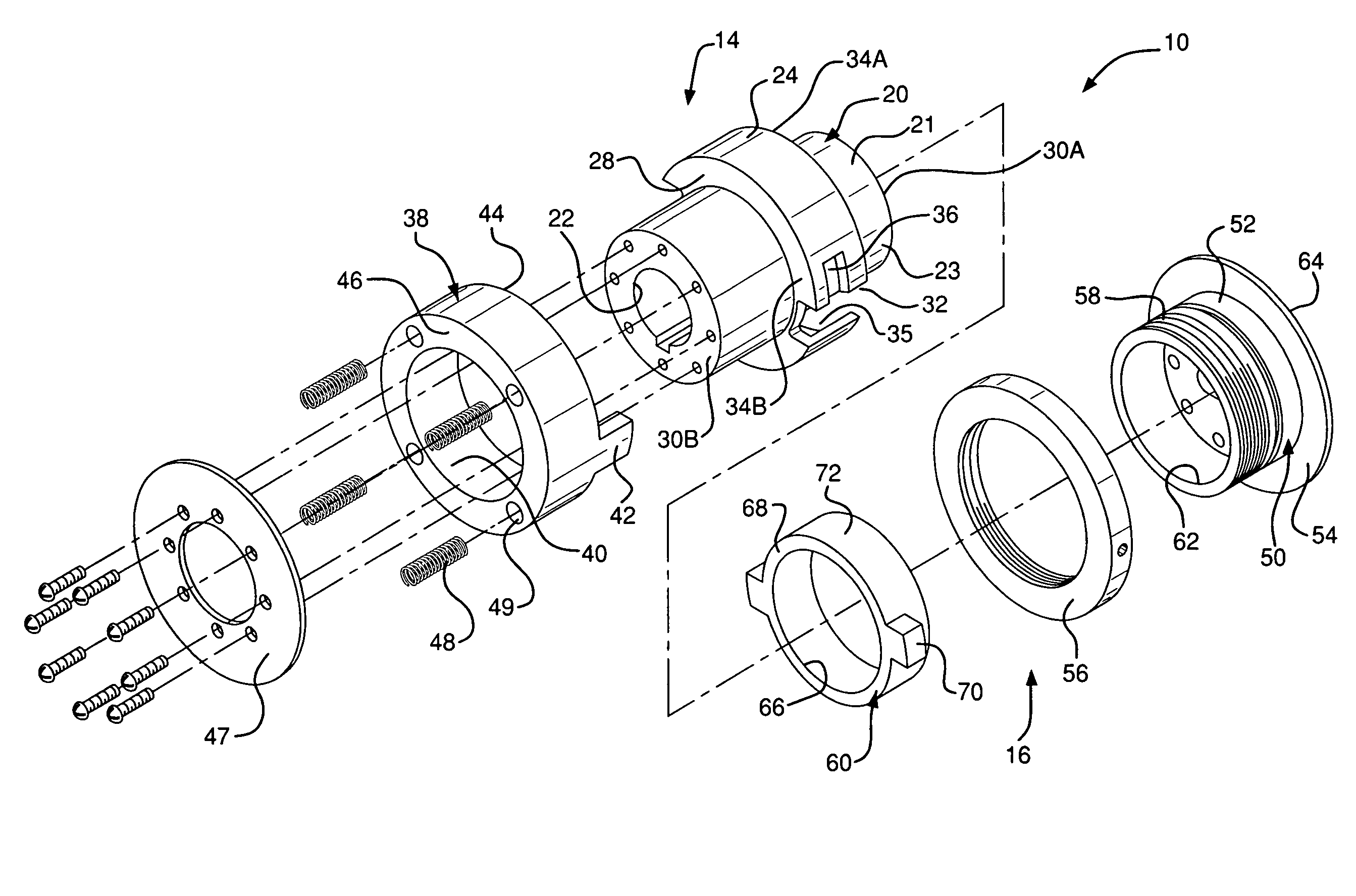
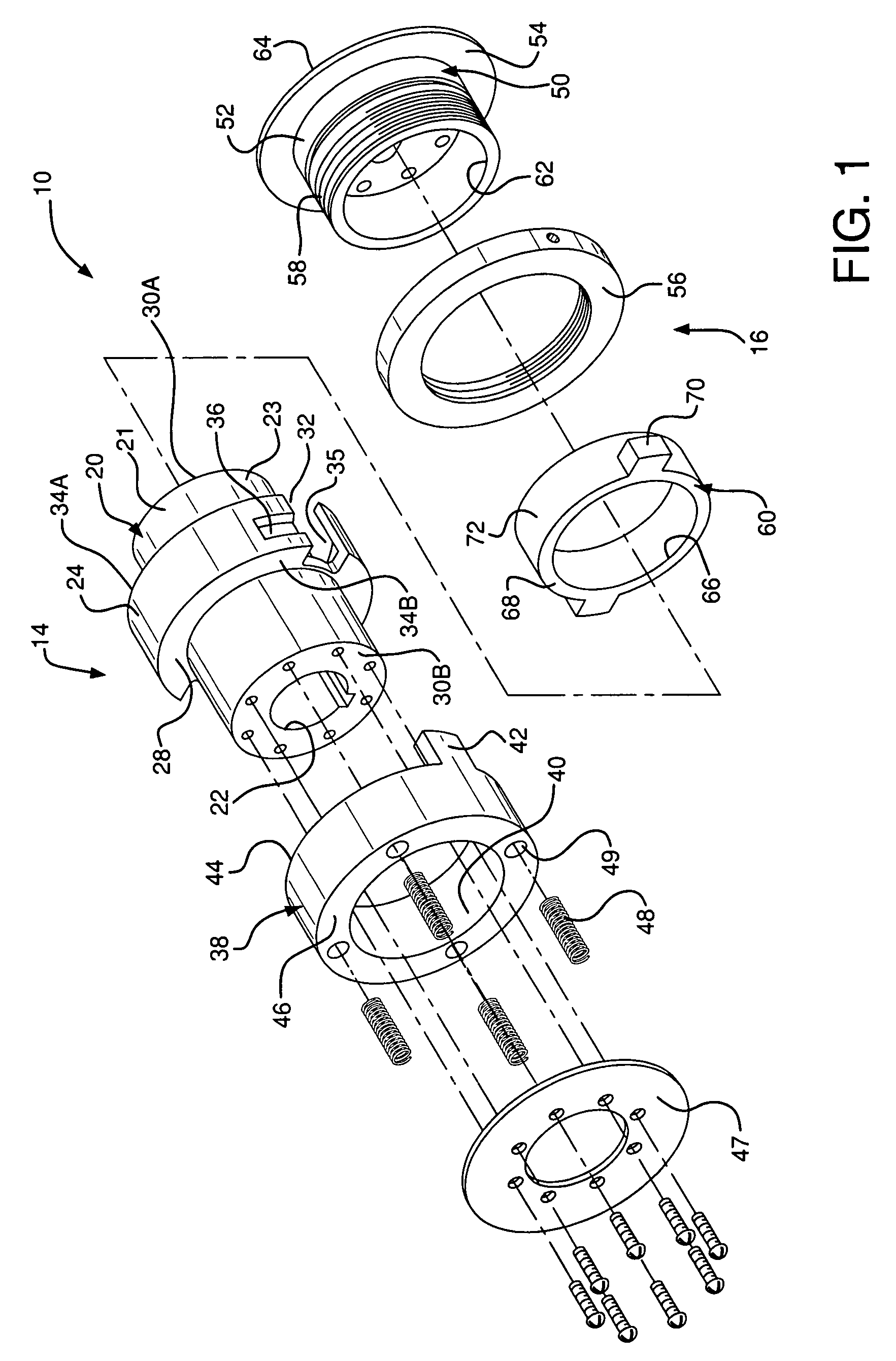
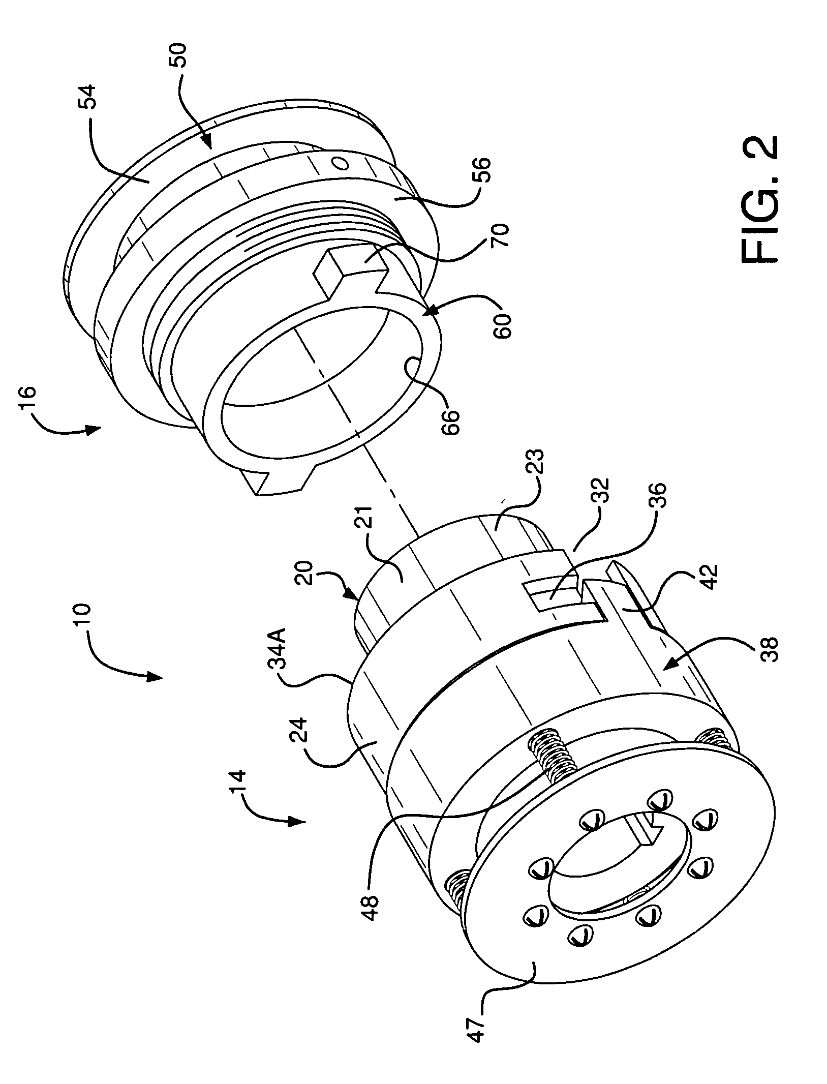
[0019]Referring now to the drawings, wherein like reference numerals illustrate corresponding or similar elements throughout the several views, FIGS. 1-4D illustrate a preferred embodiment of a quick change adapter 10 according to the present invention for mounting a finishing tool 12, such as a brush or flap disc. The quick change adapter 10 includes a shaft hub mount 14 designed to attach to a drive shaft or spindle 18 or a power driven tool, and a tool adapter mount 16 onto which the tool 12 is attached.

[0020]The shaft hub mount 14 includes a shaft sleeve 20 that has a central bore 22 extending therethrough. The central bore 22 is shaped to slide over the drive shaft 18. Preferably the drive shaft 18 has a cylindrically shape, in which case the central bore is also cylindrical in shape. However, the present invention can be configured to work on any shaft shape, including square or D-shaped drive shafts. Also, the shaft may include a locking mechanism to prevent rotation of the s...


PUM


Abstract

A quick change adapter for removeably mounting a finishing tool to a rotary drive shaft. The quick change adapter includes a shaft hub mount designed to be mounted to a rotary drive shaft, and a tool hub mount designed to hold a finishing tool and to be removably secured to the shaft hub mount. The shaft hub mount includes a shaft sleeve with an annular sleeve ring on it. An annular locking ring is biased against the sleeve ring and includes a locking tab that slides into a locking slot in the sleeve ring. The tool adapter includes a lock sleeve adapted to slide between the annular locking ring and the shaft sleeve. The lock sleeve has a locking finger this slides into a recess slot in the locking slot when the tool adapter mount is engaged with the shaft hub mount.

Description

FIELD OF THE INVENTION[0001]The invention relates to surface finishing tools and, more particularly, to a quick change adapter for mounting rotationally driven replaceable tools onto a drive spindle.BACKGROUND OF THE INVENTION[0002]Surface finishing tools are used extensively in the manufacture and repair of products. Many surface finishing tools are designed to be replaceably or interchangeably attached to a drive system. For example, wire brushes, sanding discs and flap discs wear over time and, thus, are designed to be replaceable components. These tools are removeably mounted to a spindle or drive shaft on a drive system.[0003]Generally, the replaceable tool includes a hub that is slipped over the spindle and secured, such as with a set screw. However, mounting and removing the replaceable component can be tedious, and time consuming. In a finishing operation, multiple tools may be replaced over a single work shift. As such, the downtime involved in changing tools greatly adds t...

Claims


Application Information

Patent Timeline
Patent Type & Authority Patents(United States)
IPC IPC(8): F16B7/00
CPCA46D3/08A46D9/00B24B45/006B24D13/20B24D13/145Y10T403/7005Y10T403/599Y10T403/602
Inventor SOCKMAN, JOHNBENNETT, DAVE
Owner WEILER BRUSH CO INC
Why Eureka
Try Eureka