Motor control device and vehicle including the same

a technology of motor control and control device, which is applied in the direction of electric generator control, dynamo-electric converter control, dynamo-electric gear control, etc., can solve the problems of insufficient support of hardware measures against vibration or sound noise, and inability to improve the quietness of the motor, so as to reduce vibration of the motor, increase the size and weight of the motor, and reduce the effect of vibration

Active Publication Date: 2011-09-06
DENSO CORP
View PDF27 Cites 16 Cited by
  • Summary
  • Abstract
  • Description
  • Claims
  • Application Information

AI Technical Summary

Benefits of technology

[0008]From the foregoing, the present invention was made to solve such problems, and an object of the present invention is to provide a motor control device capable of improving quietness of a motor and a vehicle including the same.
[0009]In addition, another object of the present invention is to provide a motor control device achieving improved quietness of a motor while paying attention to control stability and a vehicle including the same.
[0010]According to the present invention, a motor control device includes a current instruction generation unit and a control unit. The current instruction generation unit generates a current instruction based on a torque instruction for a motor. The control unit controls the motor based on the current instruction. The current instruction generation unit generates, based on the torque instruction, a current instruction having a current phase determined in advance for each torque of the motor so as to suppress vibration of the motor.

Problems solved by technology

In the vehicle, however, due to restricted space for mounting the motor, weight reduction or the like, measures against vibration or sound noise supported by hardware cannot sufficiently be taken in many cases.
Japanese Patent Laying-Open No. 10-328952 above, however, does not particularly take into consideration quietness of the motor, and the control method disclosed in this publication cannot improve quietness of the motor.

Method used


Image

  • Motor control device and vehicle including the same
  • Motor control device and vehicle including the same
  • Motor control device and vehicle including the same

Examples


first embodiment

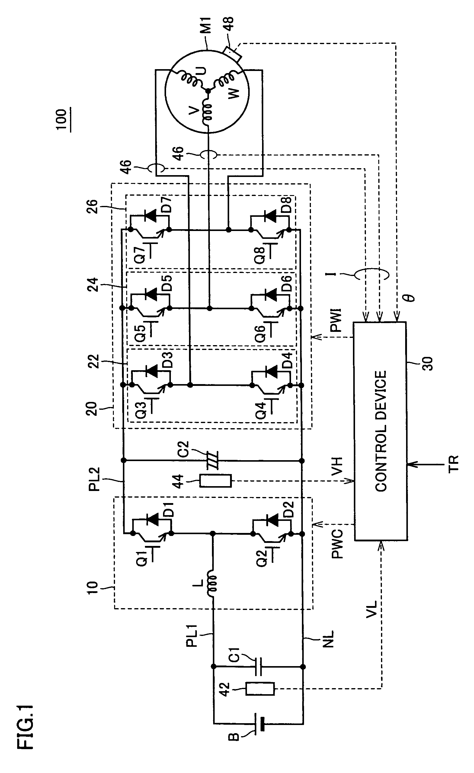
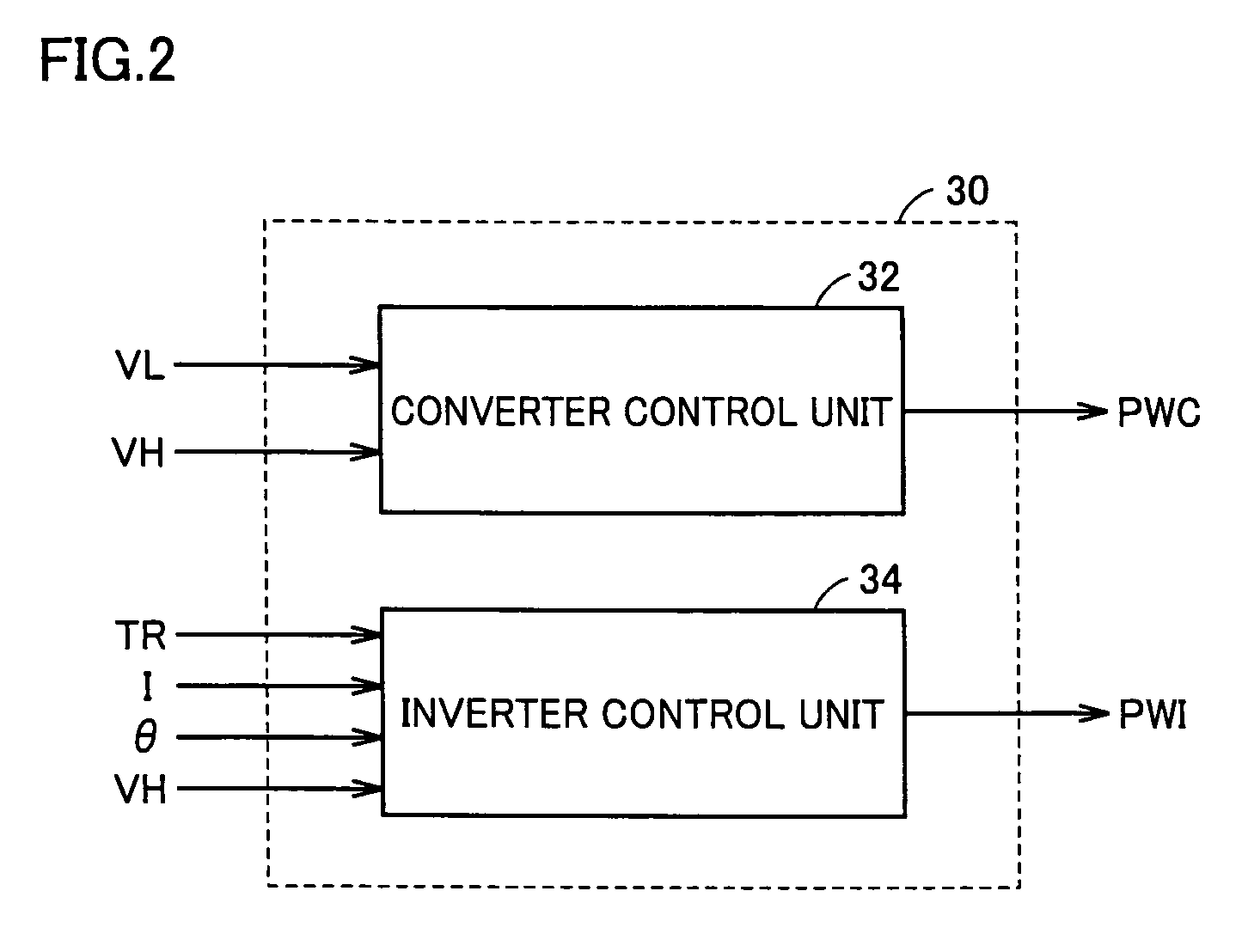
[0050]FIG. 1 is a circuit diagram of a motor drive apparatus including a motor control device according to the present invention. Referring to FIG. 1, a motor drive apparatus 100 includes a DC power supply B, a boost converter 10, an inverter 20, a control device 30, capacitors C1, C2, positive electrode lines PL1, PL2, a negative electrode line NL, voltage sensors 42, 44, a current sensor 46, and a rotation angle sensor 48.

[0051]Motor drive apparatus 100 is mounted on a vehicle such as an electric vehicle, a hybrid vehicle, a fuel cell vehicle, and the like. An AC motor M1 is mechanically linked to drive wheels (not shown) and generates torque for driving the vehicle. Alternatively, AC motor M1 may mechanically be linked to an engine (not shown) and may be incorporated in a hybrid vehicle as a generator that generates electric power using motive power of the engine and a motor starting the engine.

[0052]Boost converter 10 includes a reactor L, npn-type transistors Q1, Q2, and diodes...

second embodiment

[0096]Referring again to FIG. 7 where the current phase in low-noise control is shown with curve k17, variation in the current phase with respect to variation in the torque instruction is greater in low-noise control than in maximum torque control shown with curve k4. Here, as shown in FIG. 3, the current fed to AC motor M1 is subjected to PI control (feedback control) based on the difference between the current instruction and an actual current for each d-axis current and q-axis current. Therefore, when the current phase suddenly changes, d-axis current instruction Id* and q-axis current instruction Iq* suddenly change and control stability may be impaired. In the present second embodiment, measures for ensuring control stability while lowering noise of AC motor M1 are taken.

[0097]Referring again to FIG. 3, inverter control unit 34 in the present second embodiment includes a current instruction generation unit 102A instead of current instruction generation unit 102 in the configura...

third embodiment

[0123]FIG. 15 is a cross-sectional view of AC motor M1, schematically showing a cross-section perpendicular to a rotation axis of the motor. Referring to FIG. 15, a gap 206 is provided between a rotor 202 and a stator 204 of AC motor M1, and magnetic force F (magnetic attraction force or magnetic repulsion force) acts between rotor 202 and stator 204.

[0124]As described above, the vibration quantity of AC motor M1 is significantly dependent on magnetic force F. Here, magnetic force F that acts between rotor 202 and stator 204 can be divided into a rotation direction component Fc generating torque and a radial direction component Fr acting perpendicularly to the rotation axis. Here, fluctuation in radial direction component Fr considerably affects the vibration of AC motor M1.

[0125]FIG. 16 illustrates a manner of fluctuation of radial direction component Fr (electric sixth-order component) of magnetic force F. Referring to FIG. 16, the abscissa represents an angle of rotation of the r...


PUM


Abstract

A current instruction generation unit generates a d-axis current instruction and a q-axis current instruction based on a torque instruction for an AC motor, using a map in which a current instruction capable of lowering noise (vibration and sound noise) (low-noise current instruction) generated from the AC motor is determined in advance for each torque of the AC motor. Then, a signal for driving an inverter is generated based on the generated d-axis current instruction and the q-axis current instruction.

Description

TECHNICAL FIELD[0001]The present invention relates to a motor control device and a vehicle including the same, and more particularly to a control technique for lowering vibration and sound noise of a motor.BACKGROUND ART[0002]Current vector control for controlling a speed and torque of a motor to a desired value has conventionally been known. Various control methods have been proposed for current vector control, and for example, id=0 control, maximum torque control, field-weakening control, and the like have been known.[0003]Id=0 control refers to a control method for maintaining a d-axis current at 0, and it can readily realize linear control of torque. Maximum torque control refers to a control method for maximizing generated torque with respect to the same current, and it can efficiently generate torque. Field-weakening control refers to a control method for reducing magnetic flux in a d-axis direction by feeding a negative d-axis current, and it can broaden a speed control range...

Claims


Application Information

Patent Timeline
Patent Type & Authority Patents(United States)
IPC IPC(8): H02P21/00H02P27/06H02P6/06H02P6/08H02P21/05H02P21/22H02P23/04H02P27/04H02P27/08
CPCH02P21/0035H02P21/05H02P2207/05H02P21/22B60L15/025B60L15/20B60L2220/14H02P6/15H02P25/098Y02T10/72B60L50/51Y02T10/64Y02T10/70
Inventor HATTORI, HIROYUKIYAMADA, KENJISATO, RYOJI
Owner DENSO CORP
Why Eureka
Try Eureka