Image forming apparatus

a technology of image forming apparatus and transfer apparatus, which is applied in the direction of electrographic process apparatus, instruments, optics, etc., can solve the problems of unsatisfactory image transfer, unsatisfactory image transfer, and unsatisfactory image transfer

Active Publication Date: 2011-09-13
CANON KK
View PDF14 Cites 3 Cited by
  • Summary
  • Abstract
  • Description
  • Claims
  • Application Information

AI Technical Summary

Benefits of technology

[0009]The primary object of the present invention is to provide an image forming apparatus capable of optimizing transfer voltage to satisfactorily transfer an image even if its transferring member substantially changes in electrical resistance because of the lapse of time, temperature change, etc.

Problems solved by technology

However, in the case of a transferring apparatus which is controlled so that its transfer voltage remains stable, the transfer voltage is not adjusted every moment.
Thus, in the case of a transferring apparatus, in accordance with the prior art, controlled so that its transfer voltage remains stable, it is possible that an image is unsatisfactorily transferred due to the improper amount by which transfer current flows.
However, it was experimentally confirmed that if the electrical resistance of the transferring member substantially changes due to the lapse of time, changes in temperature, etc., an image was likely to be unsatisfactorily transferred.
That is, it was confirmed that in the case of a transferring apparatus which is controlled so that transfer voltage remains stable (constant), if its transferring member increases in resistance while the transfer voltage, the magnitude of which is roughly proportional to the resistance of the transferring member, is applied to the transferring member, the transfer voltage is likely to become excessive, whereas as the transferring member reduces in resistance, the transfer voltage is likely to become insufficient.
Thus, even if the overall amount by which current flows through the transfer area matches a target value, the effective transfer current, that is, the current which actually counts, is insufficient.
Thus, even if the overall amount by which current flows through the transfer area matches a target value, the effective transfer current, that is, the portion of the overall transfer current, which flows through the transfer area, becomes excessive.

Method used


Image

  • Image forming apparatus
  • Image forming apparatus
  • Image forming apparatus

Examples


embodiment 1

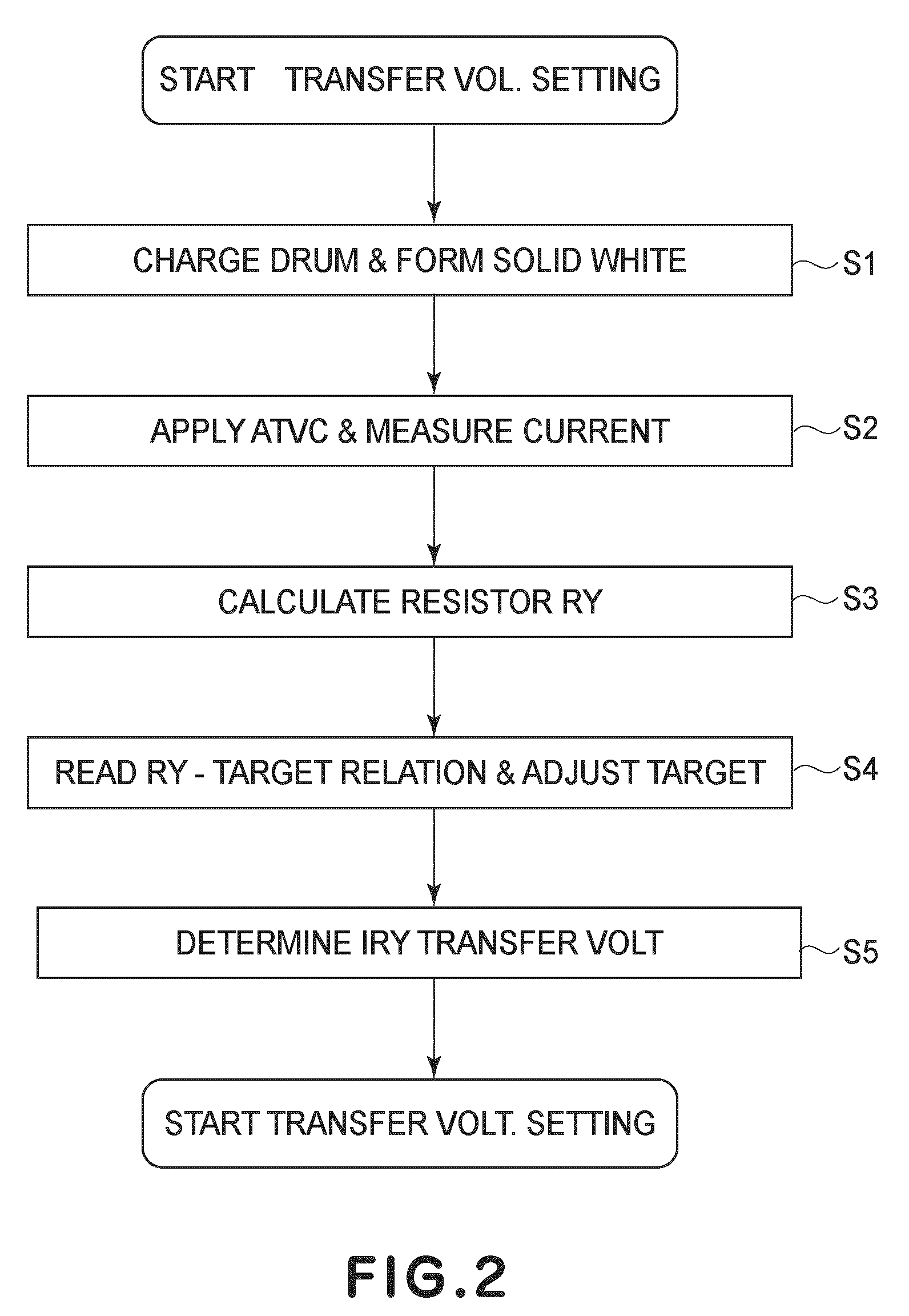
[0045]FIG. 5 is a rough drawing of the original of the solid white pattern used for ATVC. FIG. 6 is a graph showing the relationship between the amount of the voltage (for ATVC sequence) applied to the primary transfer portion, and the amount of current which flowed through the primary transfer portion. FIG. 7 is a graph showing the relationship between the electrical resistance of the primary transferring portion, and the lapse of time. FIG. 8 is a graph showing the relationship between the measured amount of transfer current and the transfer efficiency, which is used for optimizing the amount by which the transfer current is to be flowed through the primary transfer portion.

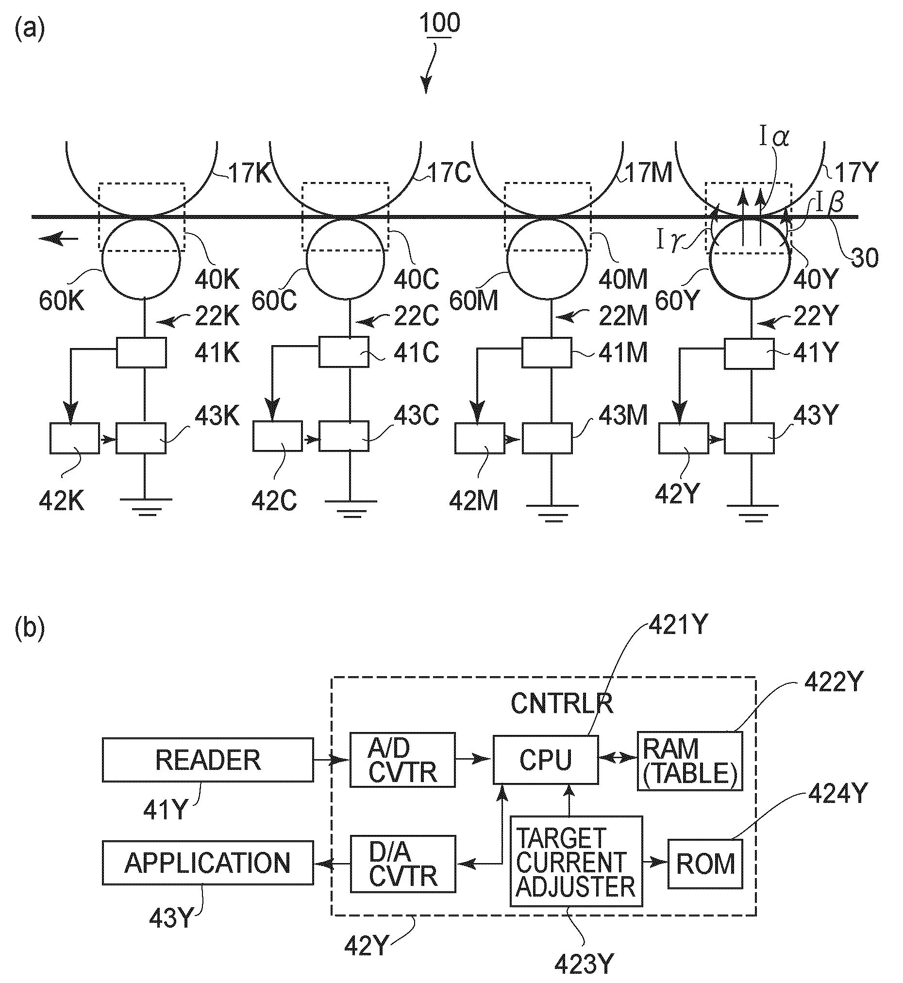
[0046]Referring to FIG. 3(a), the primary transfer voltage controlling portion (controlling means) 42Y, 42M, 42C, and 42K control the primary transfer voltage applying portions (voltage applying means) 43Y, 43M, 43C, and 43K, respectively. The primary transfer voltage controlling portions 42Y, 42M, 42C, and 42K...

embodiment 2

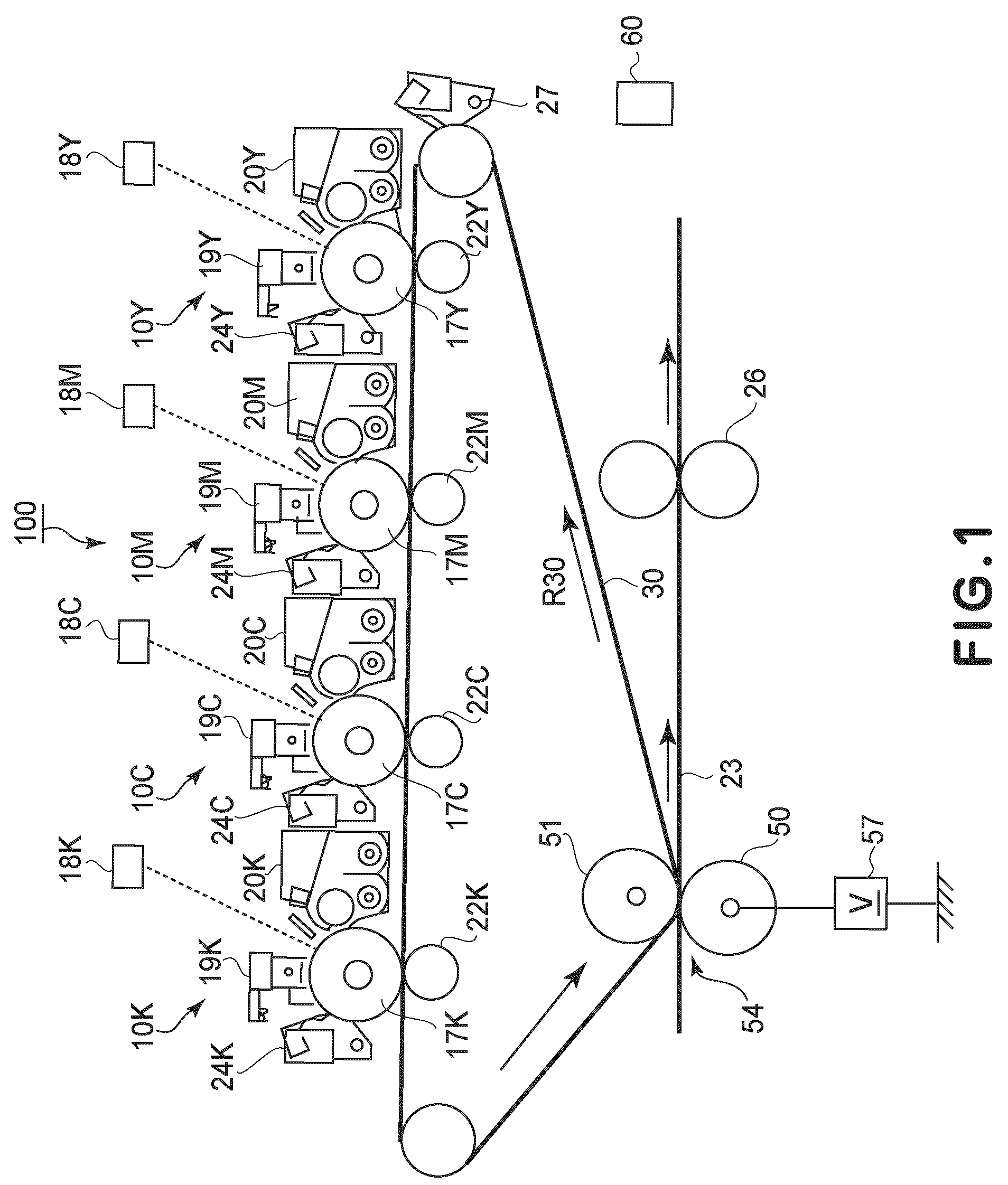
[0088]Referring to FIG. 4, a secondary transferring apparatus 53 is made up of an outside secondary transfer roller 50 and an inside second transfer roller 51 (member for backing up intermediary transferring member), which are kept pressed against each other with an intermediary transferring member 30 (which is in the form of an endless belt) sandwiched between the two rollers, forming thereby a secondary transfer nip between the intermediary transferring member 30 and the outside secondary transfer roller 50 and intermediary transferring member 30. As a secondary transfer voltage applying portion 57 (electrical bias providing means) applies voltage (secondary transfer voltage) to the outside secondary transfer roller 50 (transferring member), the toner image(s) on the intermediary transfer belt 30 is transferred (secondary transfer) onto the recording medium 23 (transfer medium) on the intermediary transfer belt 30. Incidentally, the secondary transfer roller 51 is grounded.

[0089]F...

embodiment 3

[0113]In the second embodiment, Table 2 was created so that the amount by which the transfer current is to be flowed in the ATVC sequence is optimized in response to the change in the resistance R2 of the secondary transferring portion 54. However, the amount by which transfer current flows through the secondary transferring portion 54 is also affected by the amount of toner charge per unit amount of toner, which is substantially affected by the change in the ambient condition. In this embodiment, therefore, the target value for the transfer current for the ATVC sequence is set in accordance with the resistance of the transferring portion and the change in the ambience so that an optimal amount of transfer current will flow through the transferring portion, as shown in Table 3.

[0114]

TABLE 3R2 (×108 Ω)It2(μA)−1.0−1.5−2.0−2.5. . .−4.0−4.5−5.0High58545047. . .403836Mid.68646057. . .504846Low75706562. . .555350

[0115]In terms of the structure of the secondary transferring portion 54, the...


PUM


Abstract

An image forming apparatus includes an image bearing member for carrying a toner image; a transfer member for cooperating with the image bearing member to form a nip to transfer a toner image onto a transfer medium; transfer voltage applying means for applying a transfer voltage to the transfer member to transfer the toner image; detecting means for detecting a current when a monitor voltage is applied to the transfer member; transfer voltage determining means for determining the transfer voltage on the basis of a detection result of the detecting means so that current through the transfer member in a transfer operation is the target current; and target current adjusting means for adjusting the target current so that target current when a resistance of the transfer member is relatively small is larger than the target current when the resistance value of the transfer member is relatively large.

Description

FIELD OF THE INVENTION AND RELATED ART[0001]The present invention relates to a transferring apparatus, the transfer voltage of which is optimized based on the results of the measurement of the electric current flowed through the transferring member by applying preset voltages to the transferring member to monitor the performance of the transferring apparatus. More specifically, it relates to an active transfer voltage (ATVC) control for an image forming apparatus.[0002]There has been put to practical use a full-color image forming apparatus characterized in that it uses an intermediary transfer belt or a recording medium conveying belt to sequentially place in layers multiple monochromatic images, which correspond in color to the primary colors into which the optical image of an intended color image has been separated. There have also been put to practical use an electrophotographic monochromatic image forming apparatus, and an electrophotographic full-color image forming apparatus,...

Claims


Application Information

Patent Timeline
Patent Type & Authority Patents(United States)
IPC IPC(8): G03G15/16
CPCG03G15/1605G03G15/1675G03G15/161
Inventor YAMADA, TOSHIYUKI
Owner CANON KK
Why Eureka
Try Eureka