
Clamp for corrugated tube

a technology for corrugated tubes and clamps, which is applied in the direction of snap fasteners, hose connections, machine supports, etc., can solve the problems of inability to hold corrugated tubes adequately, wobbled corrugated tubes, etc., and achieves the effects of preventing unlocking, preventing unlocking, and convenient handling

Inactive Publication Date: 2011-09-20
NEWFREY +1
View PDF12 Cites 37 Cited by
  • Summary
  • Abstract
  • Description
  • Claims
  • Application Information

AI Technical Summary

Benefits of technology

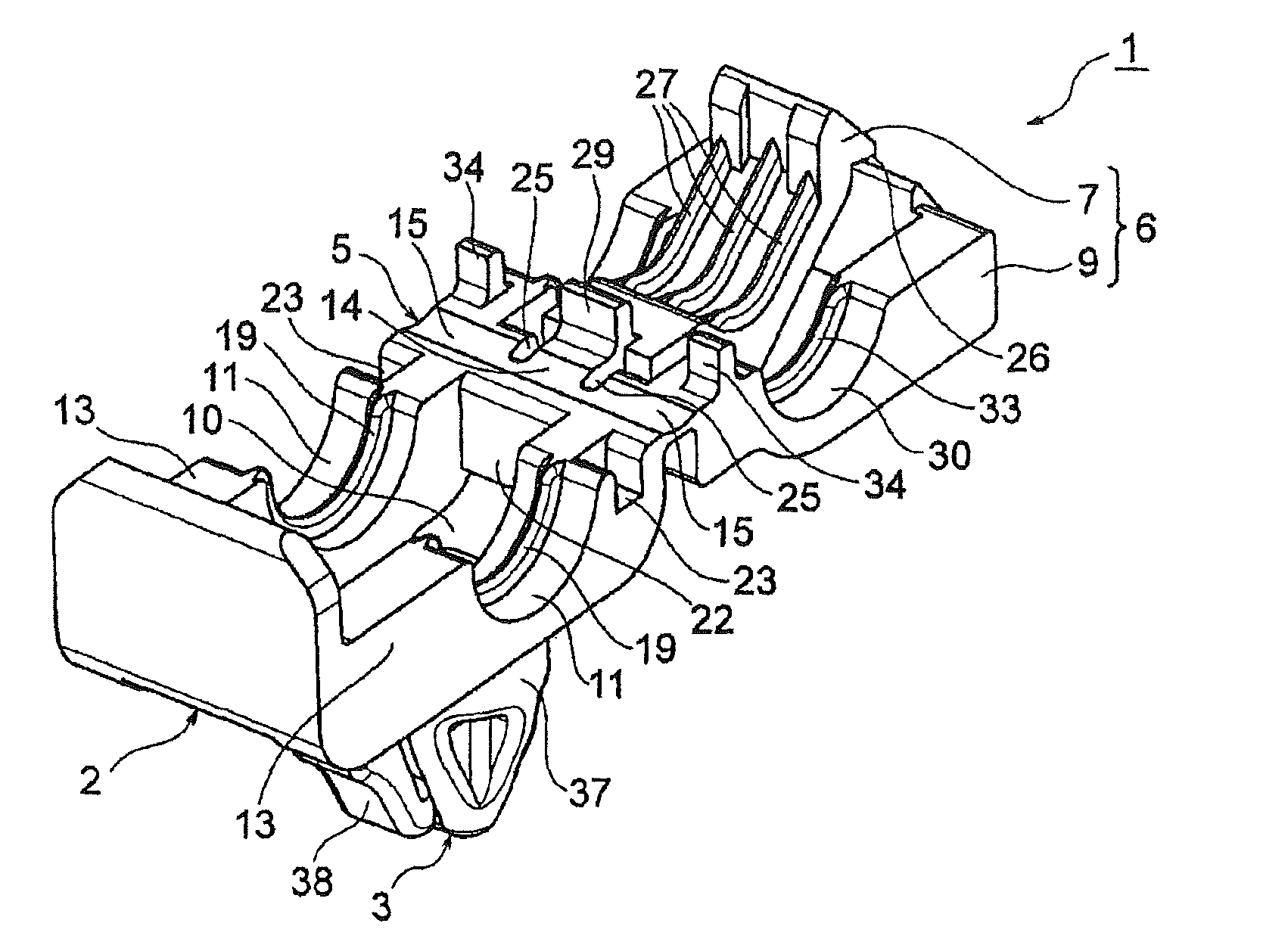
[0009]As described above, the fastener cover comprises a small corrugated tube fastener cover for pressing against a corrugated tube of small diameter and large corrugated tube fastener covers for pressing against a corrugated tube of large diameter, both fastener covers are disposed so as to be aligned in the axial direction of the corrugated tube being pressed against and held, and both, respectively, are coupled to the main fastener body by the hinge so as to be able to press against and hold corrugated tubes on the main fastener body separately. Therefore, a corrugated tube can be held with adequate holding force, whether it be a corrugated tube of large diameter or a corrugated tube of small diameter. Compared to a band clamp with which a corrugated tube is clamped with a band (cf. Patent Literature 2), moreover, the work of tightening with the band is rendered unnecessary, the time and labor for cutting off excess band [lengths] is rendered unnecessary, work time is shortened, and band waste resulting from cutting can be reduced.
[0012]When in the closed state with the cover locking means of the large corrugated tube fastener covers engaged with the main body locking means, in order to maintain a state such that the small corrugated tube fastener cover is turned on the main fastener body, a cover opening prevention surface is formed adjacent to the hinge of the large corrugated tube fastener covers, so as to come up against the end of the small corrugated tube fastener cover that is on the oppose end from the cover locking means. In this way, the two fastener covers are maintained in a closed state.
[0013]In the small corrugated tube fastener cover and the main fastener body at positions adjacent to the hinge, first guide means are formed for guiding the small corrugated tube fastener cover as it turns about the hinge. In this way, locking the small corrugated tube fastener cover in the closed state is made easy, and a definite lock is obtained, so this is highly effective in preventing unlocking.
[0014]In the large corrugated tube fastener covers and the main fastener body, at positions adjacent to the hinge, second guide means are formed for guiding the large corrugated tube fastener covers as they turn about the hinge. In this way, locking the large corrugated tube fastener covers in the closed state is made easy, and a definite lock is obtained, so this is highly effective in preventing unlocking.
[0015]In the clamp described above, moreover, the hinge is formed of a narrow, thin, panel-shaped piece that extends in the axial direction of the corrugated tube; in the panel-shaped piece between a first portion of the hinge to which the small corrugated tube fastener cover is coupled and second portions of the hinge to which the large corrugated tube fastener covers are coupled, cutouts are formed so that the small corrugated tube fastener cover and the large corrugated tube fastener covers, when they turn toward the main fastener body, turn together in the first half of that turning, but can turn separately in the latter half of the turning. In this way, when turning to the closed state, both fastener covers move together in the first half of the turning action, making handling easy, while in the latter half of turning, the holding of a corrugated tube of small diameter or large diameter can be made definite.
[0016]Ribs are formed in the main fastener body for meshing with grooves in a corrugated tube. Ribs are also formed in the small corrugated tube fastener cover for meshing with grooves in a corrugated tube of small diameter. By these ribs, a corrugated tube is held definitely, and whether a corrugated tube of large diameter or a corrugated tube of small diameter, the corrugated tube is, of course, prevented from shifting in the axial dimension, and shifting of the corrugated tube in lateral directions can also be prevented.

Problems solved by technology

With this fastener cover, when seeking to hold a corrugated tube of small diameter, the elastic pressing pieces try to press against the main fastener body, but that pressing force is small; therefore, there is a danger that the corrugated tube will wobble, and that it will not be possible to hold them adequately.

Method used


Image

  • Clamp for corrugated tube
  • Clamp for corrugated tube
  • Clamp for corrugated tube

Examples


Embodiment Construction

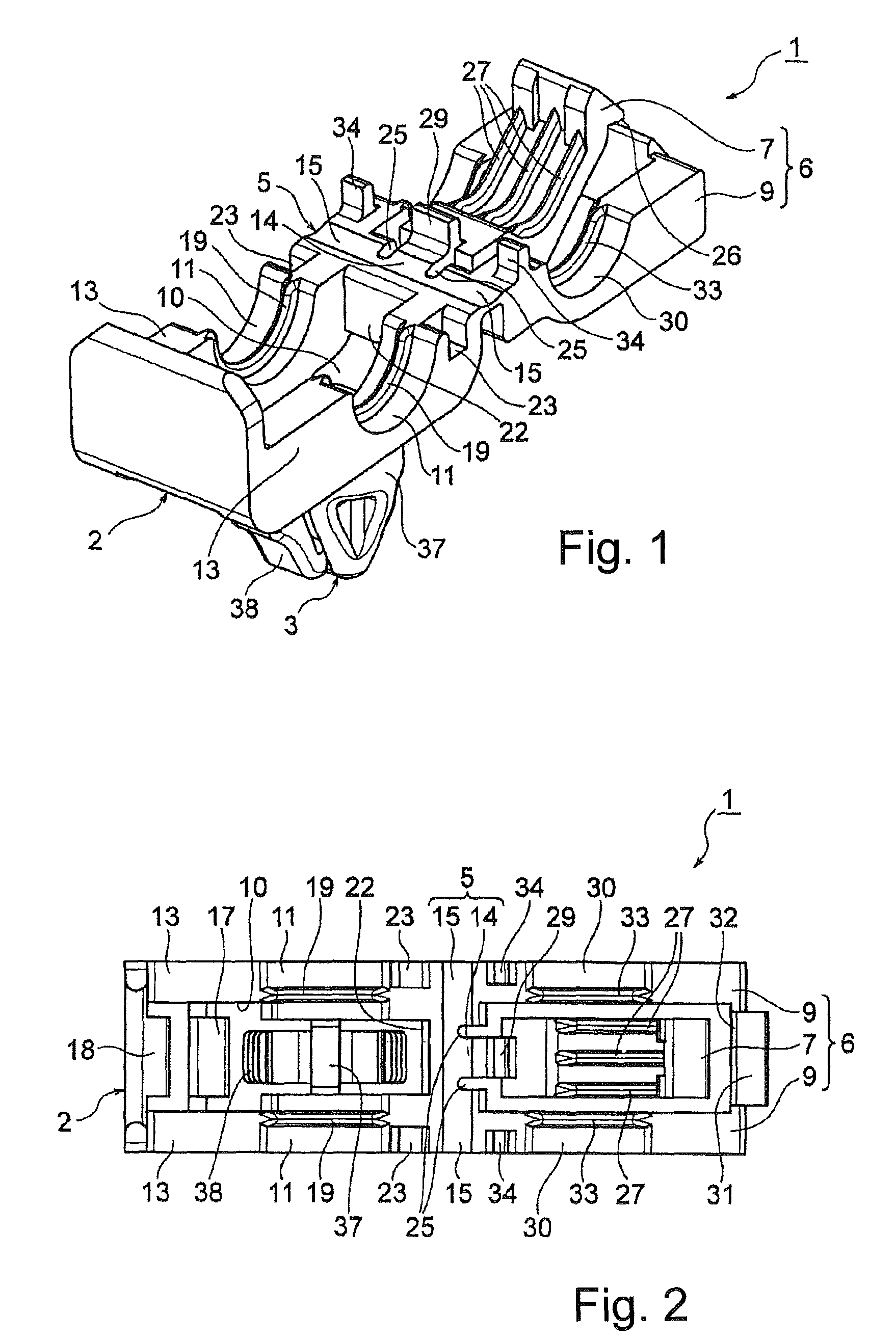
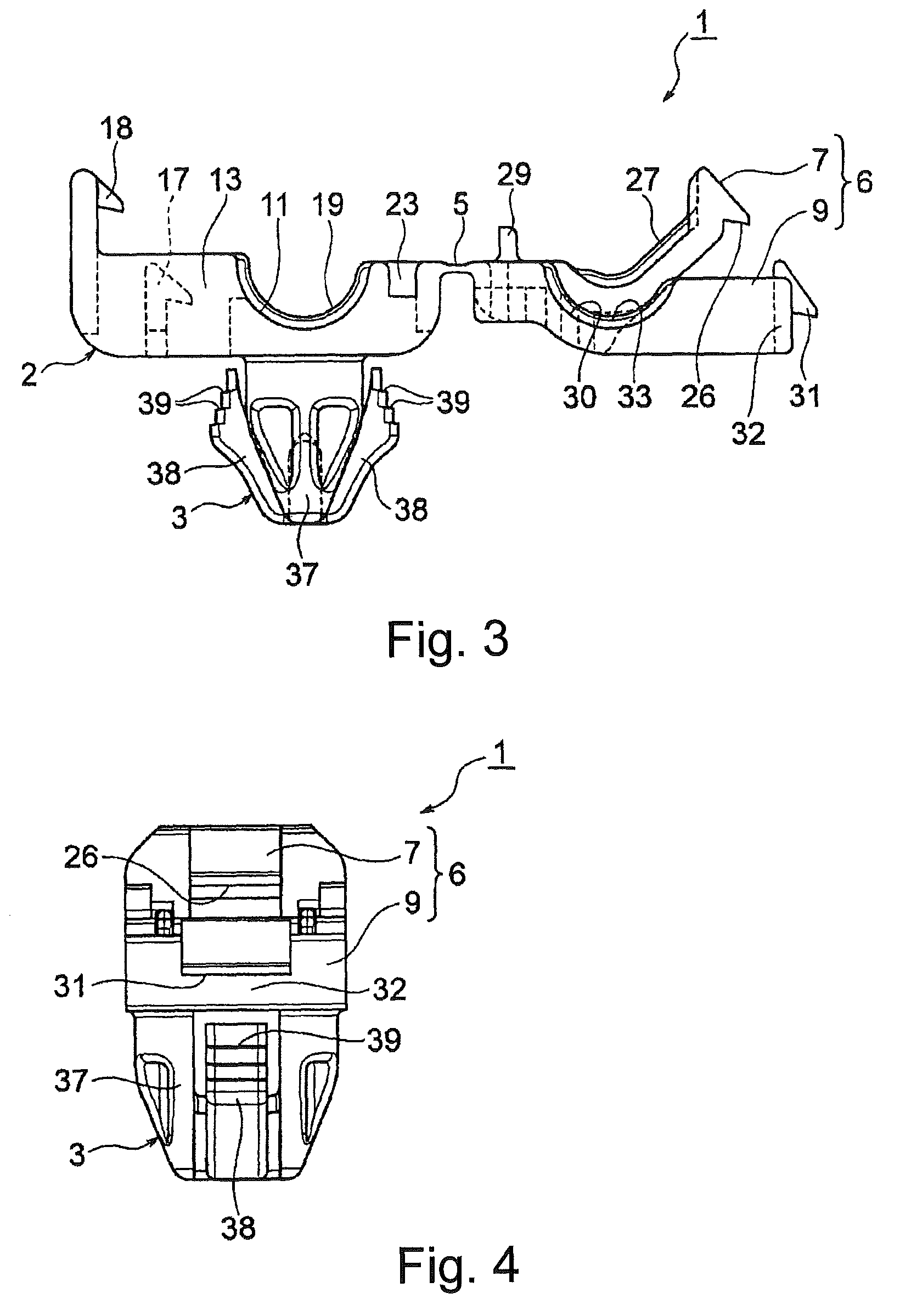
[0031]A clamp 1 for corrugated tubes that relates to one embodiment of the present invention is now described with reference to the drawings. In FIGS. 1 to 4, the clamp 1 is diagrammed in the open state wherein the upper surface of the main fastener body 2 is not covered by the fastener cover, that being the state prior to use. In FIGS. 5 and 6, a clamp 1 wherein a corrugated tube of small diameter is held is diagrammed. In FIGS. 7 to 11, a clamp 1 wherein a corrugated tube of large diameter is held is diagrammed.

[0032]In FIG. 12, a body attachment part that is attached to body panels of differing thickness is diagrammed.

[0033]The clamp 1 is now described in detail with reference to FIGS. 1 to 4. The clamp 1 is integrally formed of a hard plastic material. The clamp 1 comprises a main fastener body 2 for mounting and holding a corrugated tube, a body attachment part 3, coupled integrally to the main fastener body 2, for attaching the main fastener body to a body panel and a fastener...


PUM


Abstract

A clamp for corrugated tubes capable of holding a corrugated tube, whether a corrugated tube of large diameter or a corrugated tube of small diameter, with adequate holding force. The clamp comprises a main fastener body, a body attachment part for attaching the main fastener body to a body panel, and a fastener cover that turns about a hinge of the main fastener body and presses and holds a corrugated tube to the main fastener body, which fastener cover comprises a small corrugated tube fastener cover for pressing against a corrugated tube of small diameter, and large corrugated tube fastener covers for pressing against a corrugated tube of large diameter, which small corrugated tube fastener cover and large corrugated tube fastener covers are arranged so as to be aligned in the axial direction of the corrugated tube being pressed against and held, and which, respectively, are coupled by the hinge to the main fastener body so that, with the main fastener body, they can separately press and hold a corrugated tube on the main fastener body.

Description

CROSS REFERENCE TO RELATED APPLICATIONS[0001]The present application claims priority under 35 USC §119 to Japanese Application No. Y1P0670, filed Dec. 8, 2008, the entire contents of which are incorporated herein by reference.[0002]The present invention relates to a clamp for corrugated tubes for attaching a corrugated tube to a body panel, which clamp for corrugated tubes can hold corrugated tubes of differing diameters.BACKGROUND OF THE INVENTION[0003]Corrugated tubes have circumferential grooves aligned in multiple steps in the longitudinal direction and can withstand bending, for which reason wire harnesses and the like are often used in automobile body panels. Clamps for attaching corrugated tubes to body panels are known. A clamp for corrugated tubes described in JP H2-034883 / 1990 comprises a main fastener body for mounting and holding a corrugated tube, a body attachment part for attaching the main fastener body to a body panel and a fastener cover that is coupled by a hinge ...

Claims


Application Information

Patent Timeline
Patent Type & Authority Patents(United States)
IPC IPC(8): F16B15/00A44B11/25
CPCF16L3/1075Y10T24/344
Inventor MATSUNO, HIROTOIBARAKI, MASATO
Owner NEWFREY
Learn More