Method and system for coupling a laser with a slider in an energy assisted magnetic recording disk drive

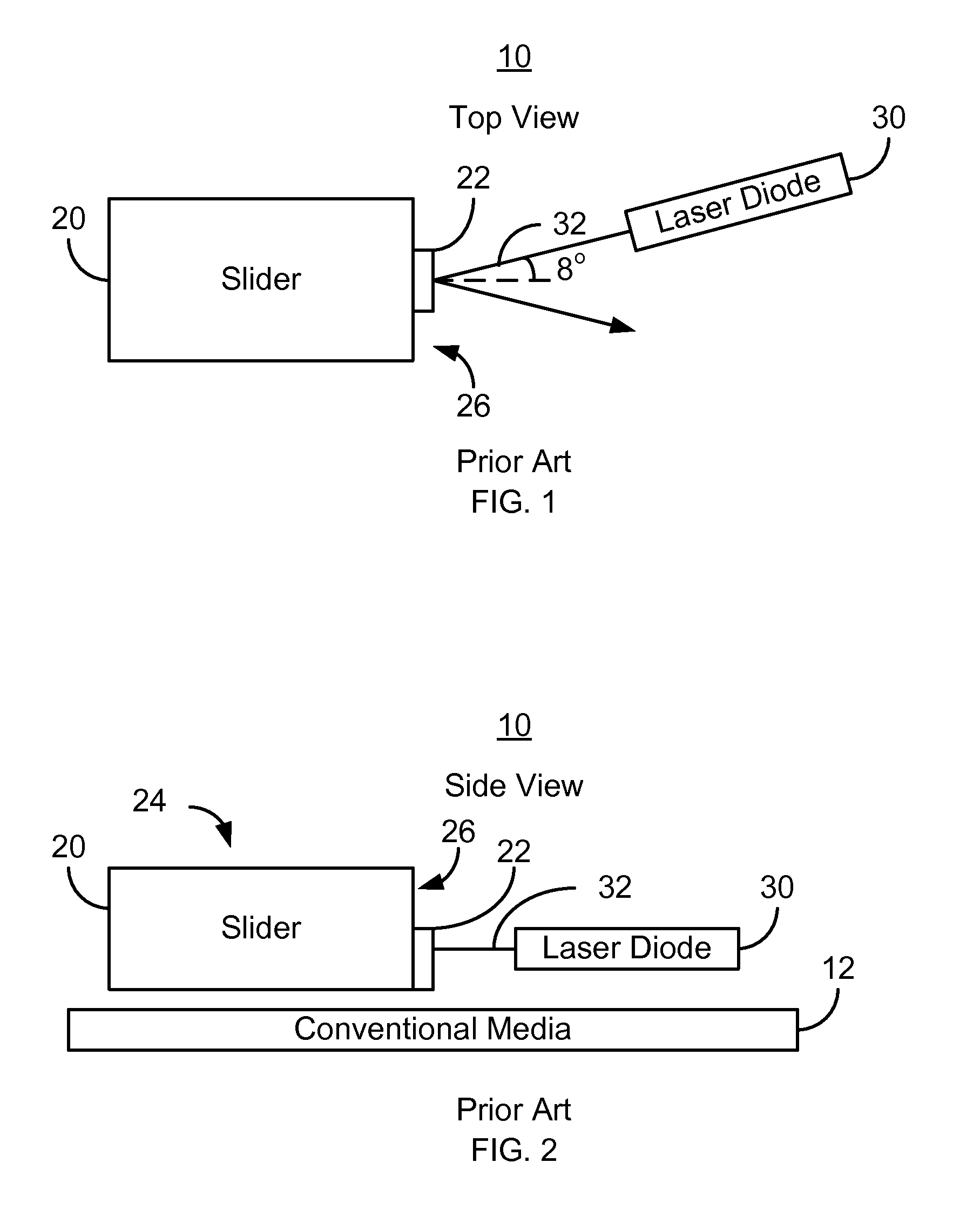
a technology of energy assisted magnetic recording and laser coupling, which is applied in the direction of special recording techniques, disposition/mounting of heads, instruments, etc., can solve the problems of difficult manufacturing of conventional eamr transducers, difficult placement of conventional sliders b>20/b> and conventional laser diodes b>30/b> using such a conventional system, and possible misalignmen

Active Publication Date: 2011-09-20
WESTERN DIGITAL TECH INC
View PDF18 Cites 174 Cited by
  • Summary
  • Abstract
  • Description
  • Claims
  • Application Information

AI Technical Summary

Benefits of technology

[0007]FIGS. 1-2 depict top and side vi

Problems solved by technology

Although the conventional EAMR transducer 10 may function, manufacturing the conventional EAMR transducer 10 may be challenging.
Accurately placing the conventional slider 20 and conventional laser diode 30 using such a conventional system may be difficult.
As a

Method used


Image

  • Method and system for coupling a laser with a slider in an energy assisted magnetic recording disk drive
  • Method and system for coupling a laser with a slider in an energy assisted magnetic recording disk drive
  • Method and system for coupling a laser with a slider in an energy assisted magnetic recording disk drive

Examples


Embodiment Construction

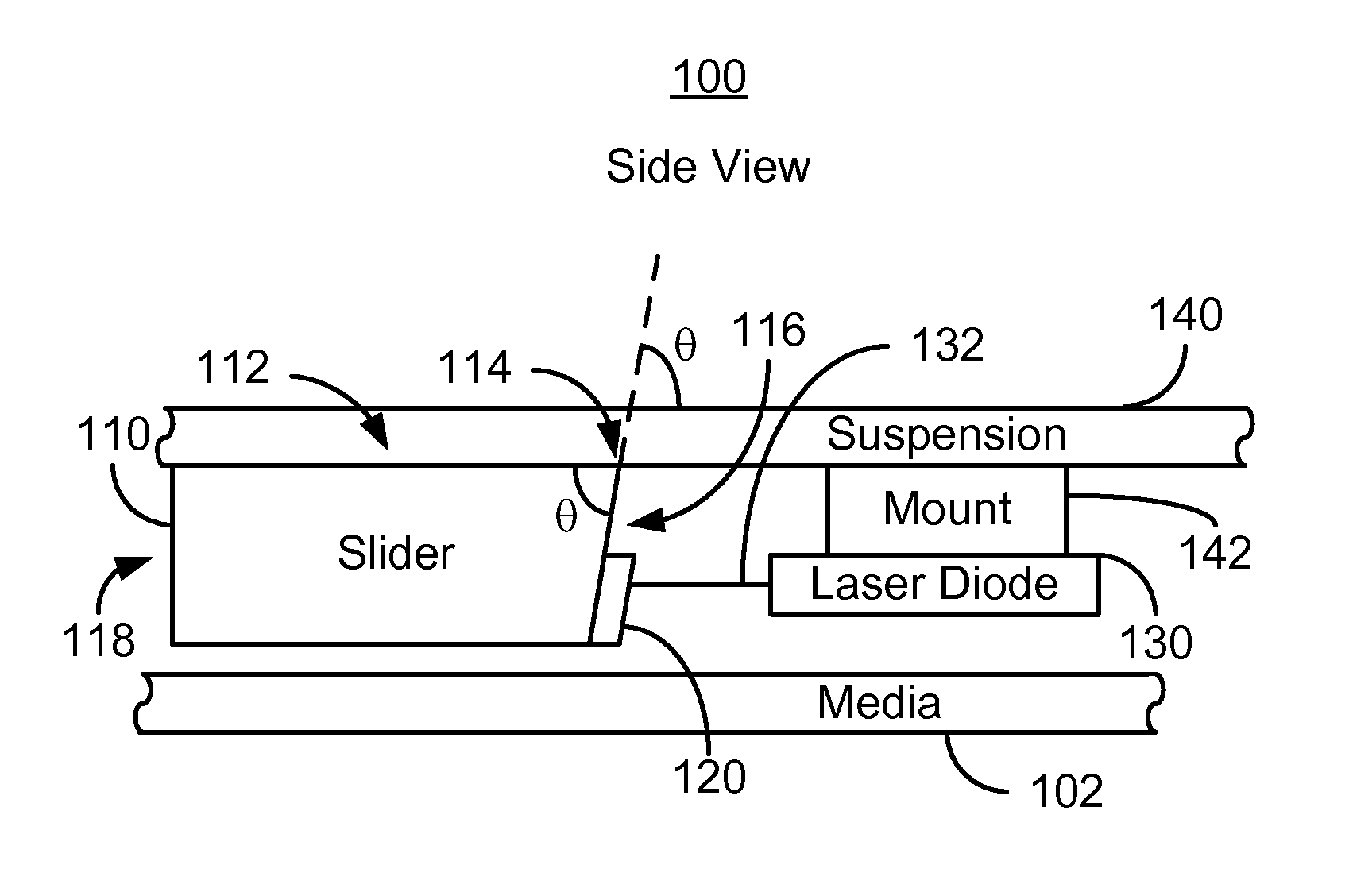
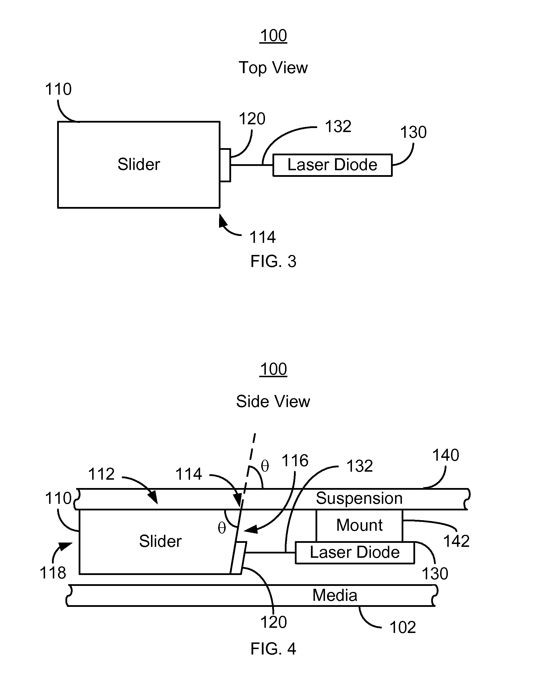
[0012]FIGS. 3 and 4 depict top and side views, respectively, of an exemplary embodiment of a portion of an EAMR disk drive 100. For clarity, FIGS. 3 and 4 are not drawn to scale. In addition, for simplicity not all portions of the EAMR disk drive 100 are shown. In addition, although the head 100 is depicted in the context of particular components other and / or different components may be used. The EAMR disk drive 100 includes media 102, a slider 110, an EAMR transducer 120, a laser 130 and a suspension 140. The slider 110 includes a back side 112, a trailing face 116, an intersection 114, and a leading face 118. The intersection 114 is an edge at which the trailing face 116 and slider back side 112 meet. The slider back side 112 and trailing face 116 meet at an angle θ at the intersection 114. As can be seen in FIG. 4, θ is different from 90°. In some embodiments, θ is not more than at least 75° and less than 90°. In some such embodiments, θ is greater than or equal to at least 81.3°...


PUM


Abstract

A method and system for providing an energy assisted magnetic recording (EAMR) disk drive are described. The EAMR disk drive includes a slider, at least one EAMR transducer on the slider, and at least one laser coupled with the slider. The slider has a slider back side, a trailing face, and an intersection. The trailing face and the slider back side meet at the intersection. The trailing face makes an angle different from ninety degrees with the slider back side at the intersection. The laser(s) have an optical axis and are optically coupled with the trailing face of the slider. The optical axis is substantially perpendicular to the intersection and parallel to the slider back side.

Description

BACKGROUND[0001]FIGS. 1-2 depict a portion of a conventional energy assisted magnetic recording (EAMR) disk drive 10. Top and side views are shown in FIGS. 1 and 2, respectively. The conventional EAMR disk drive 10 includes a recording media 12, a conventional slider 20, and a conventional laser diode 30 that are typically attached to a suspension (not shown). Other components that may be part of the conventional EAMR disk drive 10 are not shown. The conventional slider 20 includes a back side 24 and a trailing face 26. The conventional slider 20 is typically attached to the suspension at its back side 24. A conventional EAMR transducer 22 is coupled with the slider 20 on the trailing face 26 of the slider. As can be seen in FIG. 2, the trailing face 26 and back side 24 of the slider 20 are typically perpendicular.[0002]The conventional EAMR transducer 22 includes a grating (not separately shown) on the trailing face 26. Light from the conventional laser diode 30 is provided substan...

Claims


Application Information

Patent Timeline
IPC IPC(8): G11B7/08G11B11/00
CPCG11B5/314G11B2005/001G11B2005/0021
Inventor MORAVEC, MARK D.NONTPRASAT, ANUCHA
Owner WESTERN DIGITAL TECH INC
Why Eureka
Try Eureka