
Imaging system for endoscopic surgery

a technology for endoscopic surgery and imaging system, applied in the field of imaging system, can solve problems such as field of view, adversely affecting an ongoing procedure, and stereotactical system not working well

Active Publication Date: 2011-09-27
DANNAN PATRICK
View PDF8 Cites 219 Cited by
  • Summary
  • Abstract
  • Description
  • Claims
  • Application Information

AI Technical Summary

Benefits of technology

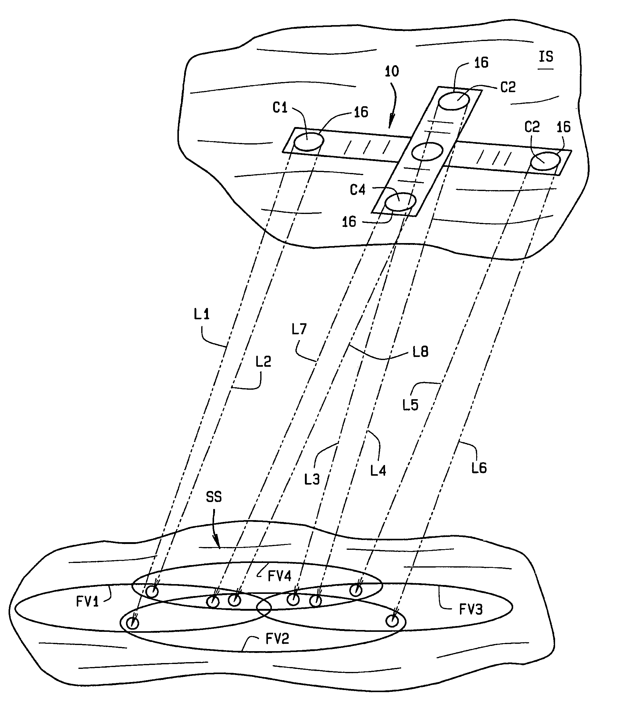
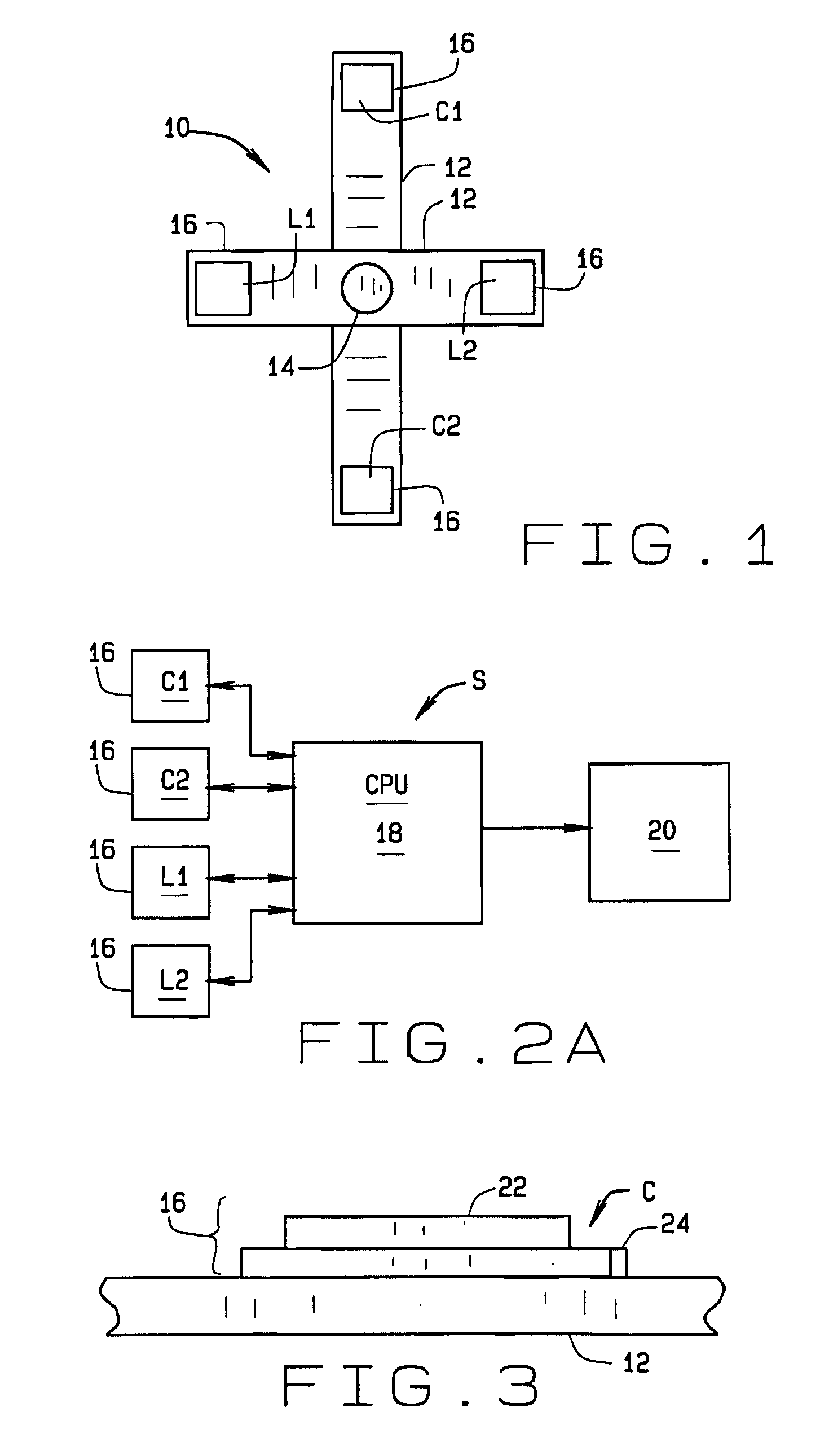
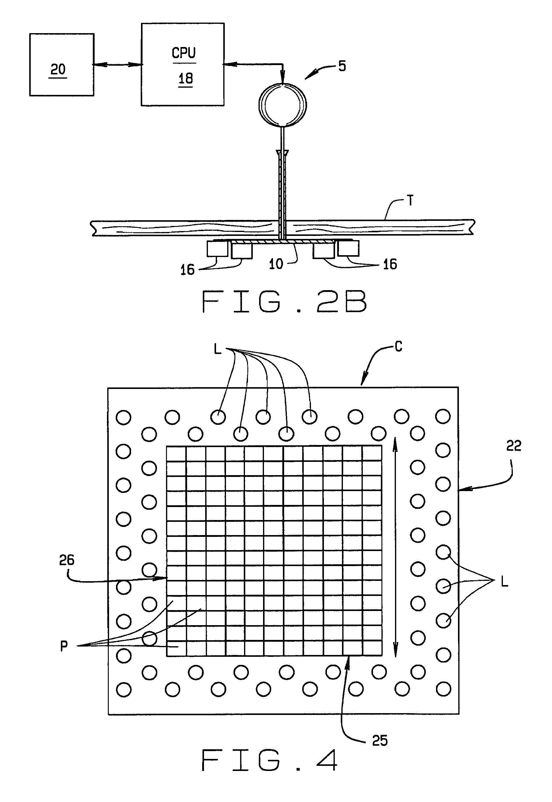
[0007]The present invention relates to an imaging system for providing practitioners with an image of a surgical site within a patient cavity during minimally invasive surgery. An illustrative embodiment of the imaging system comprises (a) a plurality of sensors and transmitters adapted to be anchored to a wall of the cavity; b) a plurality of lasers operable to direct a laser beam towards the surgical site; c) means for converting the data from the sensors into image data; and d) means for comparing the image data from two or more sensors to align the image data from the sensors to produce a single unified image. The transmitters are operable to emit a selected form of energy towards the surgical site and the sensors receive reflected energy from the surgical site. The sensors then emit data indicative of the information detected by the

Problems solved by technology

As can be appreciated, a changing field of view can adversely impact an ongoing procedure.
However, in surgical sites, such as the abdominal or thoracic cavities, for example, where the tissues are softer and movement of the tissues at the surgical site or movement of the cavity wall during a procedure are likely, such stereotactical systems will not work well.

Method used


Image

  • Imaging system for endoscopic surgery
  • Imaging system for endoscopic surgery
  • Imaging system for endoscopic surgery

Examples


Embodiment Construction

[0015]The following detailed description illustrates the invention by way of example and not by way of limitation. This description will clearly enable one skilled in the art to make and use the invention, and describes several embodiments, adaptations, variations, alternatives and uses of the invention, including what I presently believe is the best mode of carrying out the invention. Additionally, it is to be understood that the invention is not limited in its application to the details of construction and the arrangements of components set forth in the following description or illustrated in the drawings. The invention is capable of other embodiments and of being practiced or being carried out in various ways. Also, it is to be understood that the phraseology and terminology used herein is for the purpose of description and should not be regarded as limiting.

[0016]An illustrative embodiment of an imaging system 5 of the present invention includes a platform 10 which is anchored i...


PUM


Abstract

An imaging system is provided for use with minimally invasive surgery. The imaging system comprises a platform which is anchored to a wall of a patient cavity. The platform comprises a plurality of transceivers which transmit energy toward the surgical site and receive reflected energy. The transceivers transmit rasterized image information to a computer which then displays the image information in real time, enabling a surgeon to view the surgical site on a display device. The transceivers can transmit and receive different types of energy, and the computer can then combine image information from the various different energy types to provide overlaid images of the surgical site. In addition, the computer controls the relative positions of the transceivers so that the images provided to the surgeon will not be affected by movement of the platform or by movement of structures (i.e., organs) at the surgical site.

Description

CROSS-REFERENCE TO RELATED APPLICATIONS[0001]The application claims priority to U.S. Provisional App. No. 60 / 648,349 filed Jan. 28, 2005 and which is incorporated herein by reference.STATEMENT REGARDING FEDERALLY SPONSORED RESEARCH OR DEVELOPMENT[0002]Not Applicable.BACKGROUND OF THE INVENTION[0003]This application relates to imaging systems for use in devices for use in minimally invasive or endoscopic surgery.[0004]Endoscopic or minimally invasive surgery has become fairly common and is becoming more and more common as surgeons learn and advance endoscopic technology and techniques. Currently, endoscopic surgery is used for procedures conducted in the sinus cavities, on the spine, on knees, on feet, in the abdominal cavity, and in the thoracic cavity. As the technology (i.e., the surgical instruments) and techniques advance, endoscopic surgery will become even more prevalent.[0005]Minimally invasive or endoscopic surgery, as is known, is conducted in a cavity within the patient's ...

Claims


Application Information

Patent Timeline
IPC IPC(8): A61B5/05
CPCA61B1/00009A61B1/04A61B1/313A61B5/1076A61B19/52A61B5/06A61B19/5202A61B19/5212A61B2017/00296A61B2019/5276A61B2019/5289A61B2017/00283A61B90/36A61B90/30A61B2090/364A61B90/361A61B2090/378
Inventor DANNAN, PATRICK
Owner DANNAN PATRICK
Learn More