
Cutting head for a brush cutter, edge trimmer or similar

Active Publication Date: 2011-10-04
SPEED FRANCE SAS
View PDF19 Cites 6 Cited by
  • Summary
  • Abstract
  • Description
  • Claims
  • Application Information

AI Technical Summary

Benefits of technology

[0009]One of the objects of the invention is thus to remedy these drawbacks by proposing a cutting head for a brush cutter, edge trimmer, or similar comprising at least one cutting string strand passageway and a locking element of said cutting string of simple design, low cost and achieving the locking of smooth and / or toothed cutting string strand.

Problems solved by technology

Besides a high production cost induced by the stop, it is difficult to replace the cutting string onto the cutting head described above in the course of use because the user is generally wearing gloves.

Method used


Image

  • Cutting head for a brush cutter, edge trimmer or similar
  • Cutting head for a brush cutter, edge trimmer or similar
  • Cutting head for a brush cutter, edge trimmer or similar

Examples


Embodiment Construction

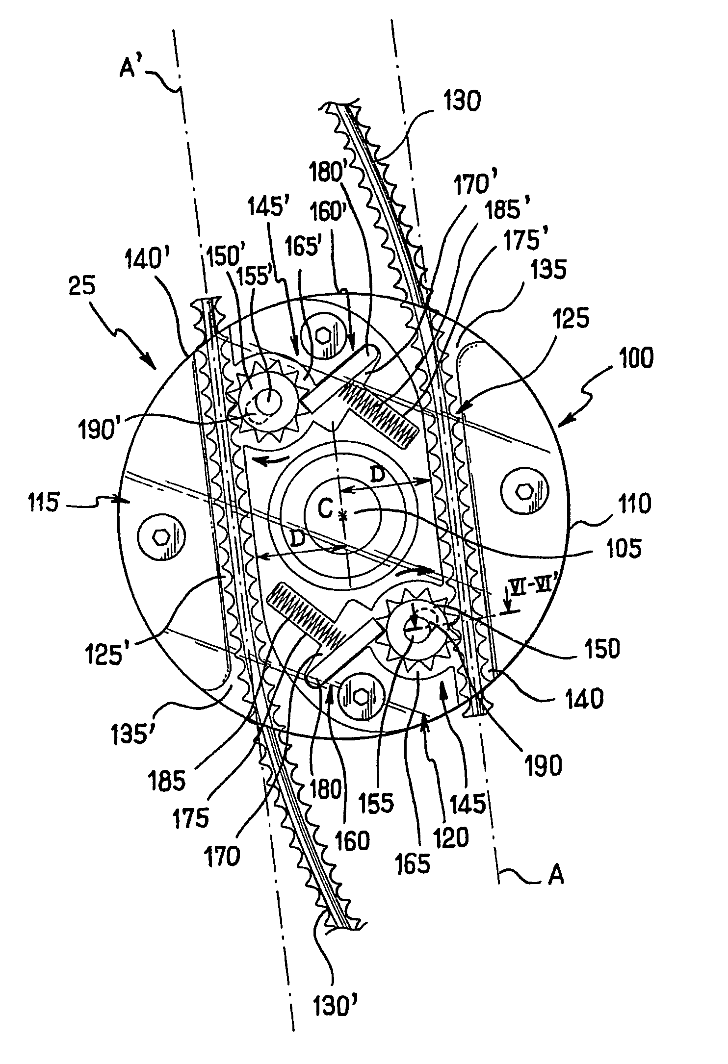
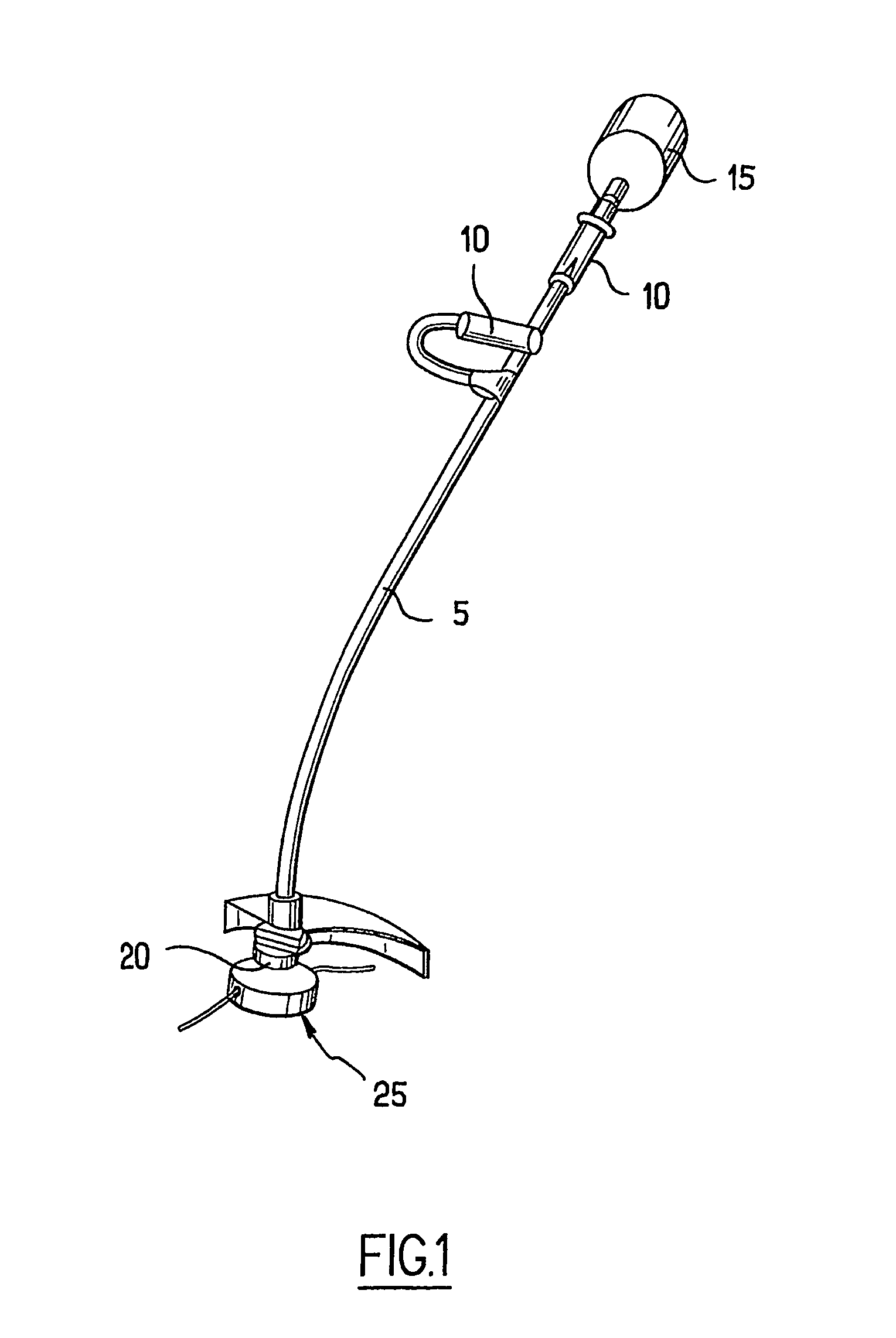
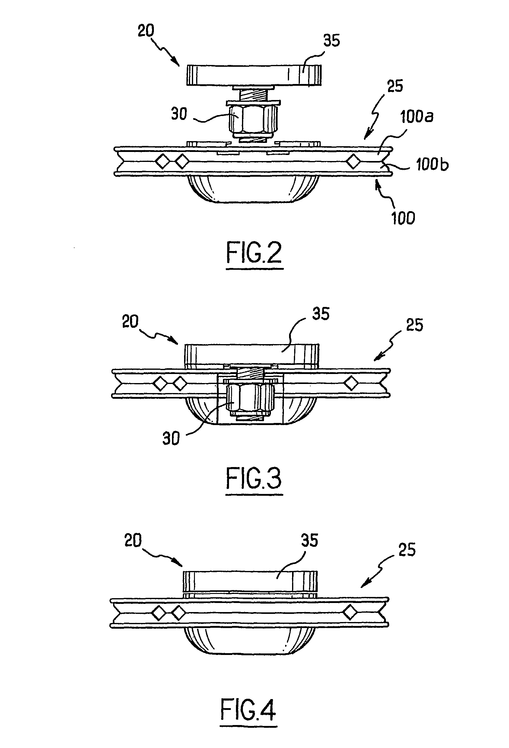
[0020]Referring to the drawings, wherein like reference numerals represent like elements, there is shown in FIG. 1 a brush cutter. The brush cutter usually comprises a shaft 5 including handles 10 and an electric or heat engine 15 driving a drive shaft 20, a cutting head 25 being mounted at the distal end of the drive shaft 20. FIGS. 1-3 represent a cutting head 25 for a brush cutter, edge trimmer, and similar according to the invention, the cutting head suitable for being mounted on the extremity of a drive shaft 20. The drive shaft 20 is provided for the purpose of fixing arrangements 30 such as washer, nut, mechanism of indexation in rotation, as well as a counterplate 35, intended to cooperate with the fixing arrangements in a manner completely conventional in itself.

[0021]The cutting head 25 is implemented here by overlaying and assembling two disc-shaped parts 100a and 100b concentric with the axis of rotation of the drive shaft 20. Each disc-shaped part 100a and 100b comprise...


PUM


Abstract

The invention relates to a cutting head for a brush cutter, edge trimmer or similar, the head being of the type including at least a passageway for a cutting string and a locking element of the cutting string. The cutting head is characterized in that the locking elements include at least one ratchet wheel, including a toothed wheel mounted in rotation around an axis in such a manner that said teeth project in the passageway. The ratchet can be arranged in such a way that the toothed wheel can turn in a given direction to allow the introduction of the cutting string in the passageway and cannot turn in the opposite direction, thereby locking the cutting string in the passageway.

Description

CROSS-REFERENCE TO RELATED APPLICATIONS[0001]The present application is a national phase entry under 35 U.S.C. §371 of International Appln. No. PCT / IB2007 / 002750 filed May 15, 2007, the disclosure of which is hereby incorporated herein by reference.FIELD OF THE INVENTION[0002]The present invention relates in general to the field of spinning-string implements for cutting vegetation, such as mowers, trimmers, etc., and more particularly to a locking element in order to hold firmly the string relative to the rotary cutting head on which they are mounted.BACKGROUND OF THE INVENTION[0003]Portable apparatus for cutting vegetation are well known in the art. Such apparatus generally comprise a heat engine or an electric engine at the end of a shaft. The engine, located at the vicinity of a handle, drives in rotation at a high speed of generally about several thousand rounds per minute. A cutting head holds one or a plurality of cutting strings. The one or the plurality of cutting strings ex...

Claims


Application Information

Patent Timeline
IPC IPC(8): A01D34/416
CPCA01D34/4166
Inventor LEGRAND, EMMANUEL
Owner SPEED FRANCE SAS
Learn More