Webbing take-up device

a take-up device and webbing technology, applied in mechanical devices, transportation and packaging, gearing, etc., can solve the problems of reducing the cost of the device or realizing a light-weight device, and achieve the effect of reducing the cost and improving the extra strength of the components

Active Publication Date: 2011-10-04
KK TOKAI RIKA DENKI SEISAKUSHO
View PDF21 Cites 2 Cited by
  • Summary
  • Abstract
  • Description
  • Claims
  • Application Information

AI Technical Summary

Benefits of technology

[0023]As described above, the webbing take-up device according to the present invention has an excellent effect that not only the take-up shaft can be rotated by the motor, but also no improvement in extra strength of components is required, and a light-weight and small-size device and cost reduction of the device can be realized.

Problems solved by technology

This results in that realization of a light-weight device or cost reduction of the device would be impeded.Patent document 1: JP-A No. 2001-130376Patent document 2: JP-A No. 2001-347923

Method used


Image

  • Webbing take-up device
  • Webbing take-up device
  • Webbing take-up device

Examples


Embodiment Construction

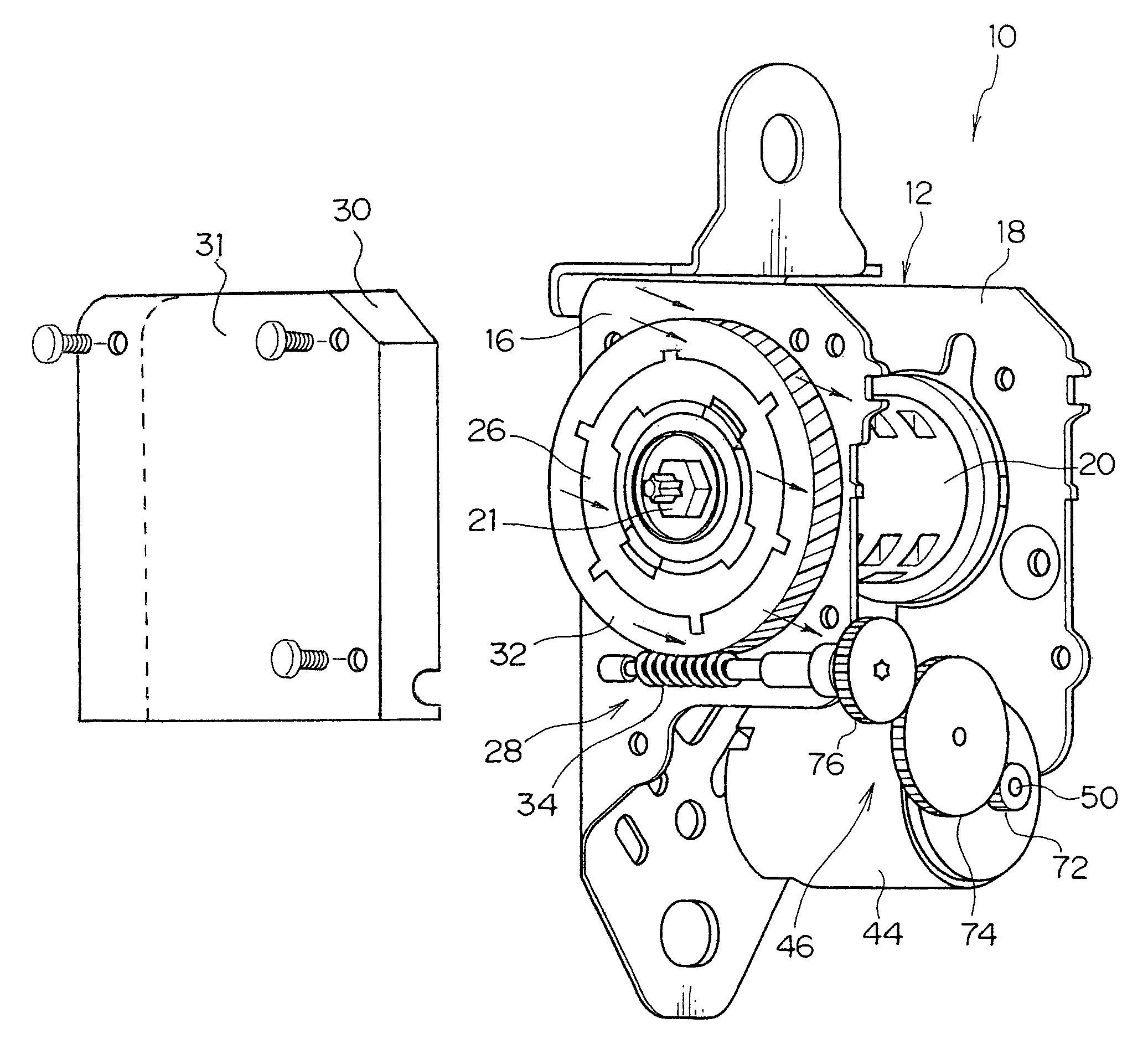
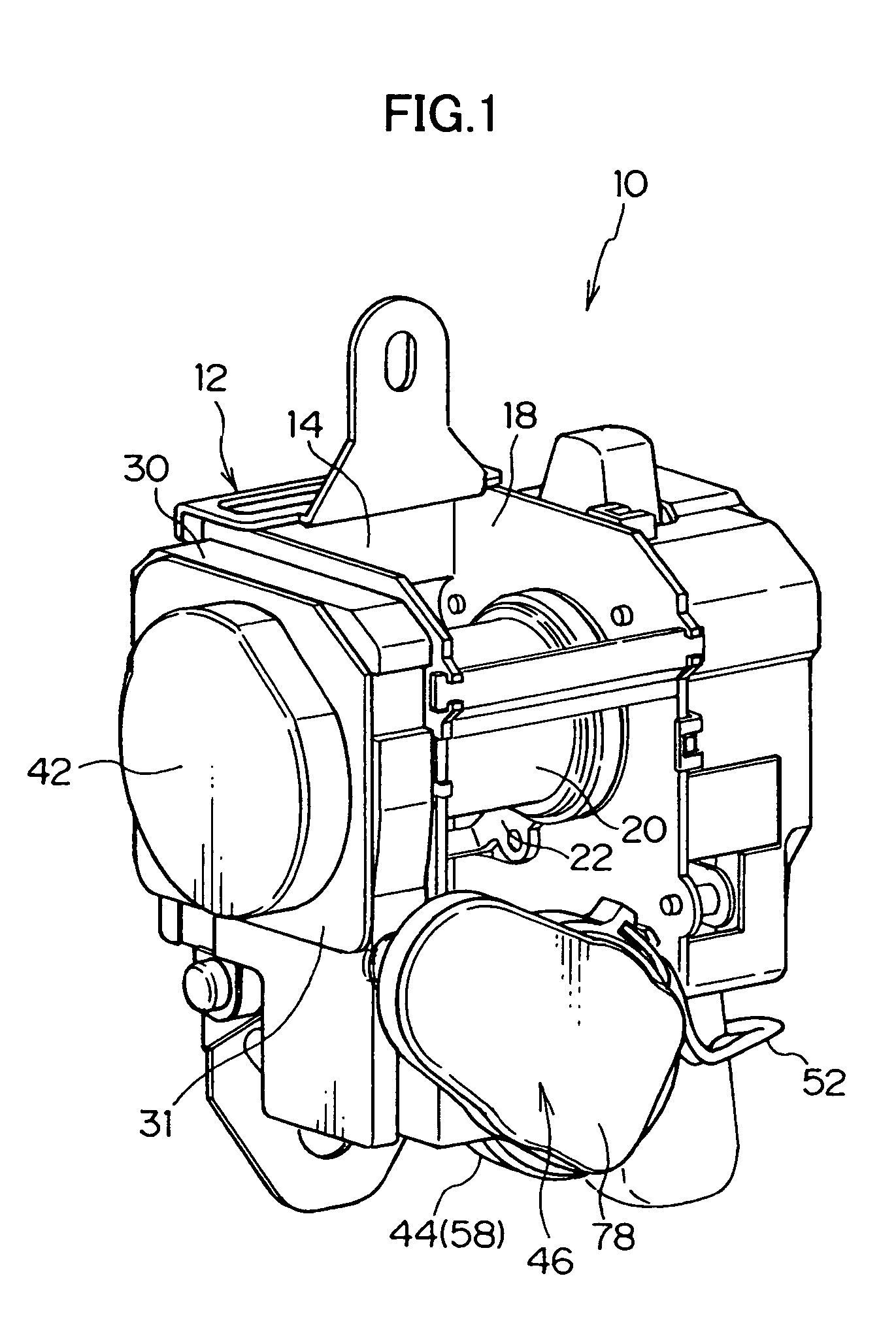
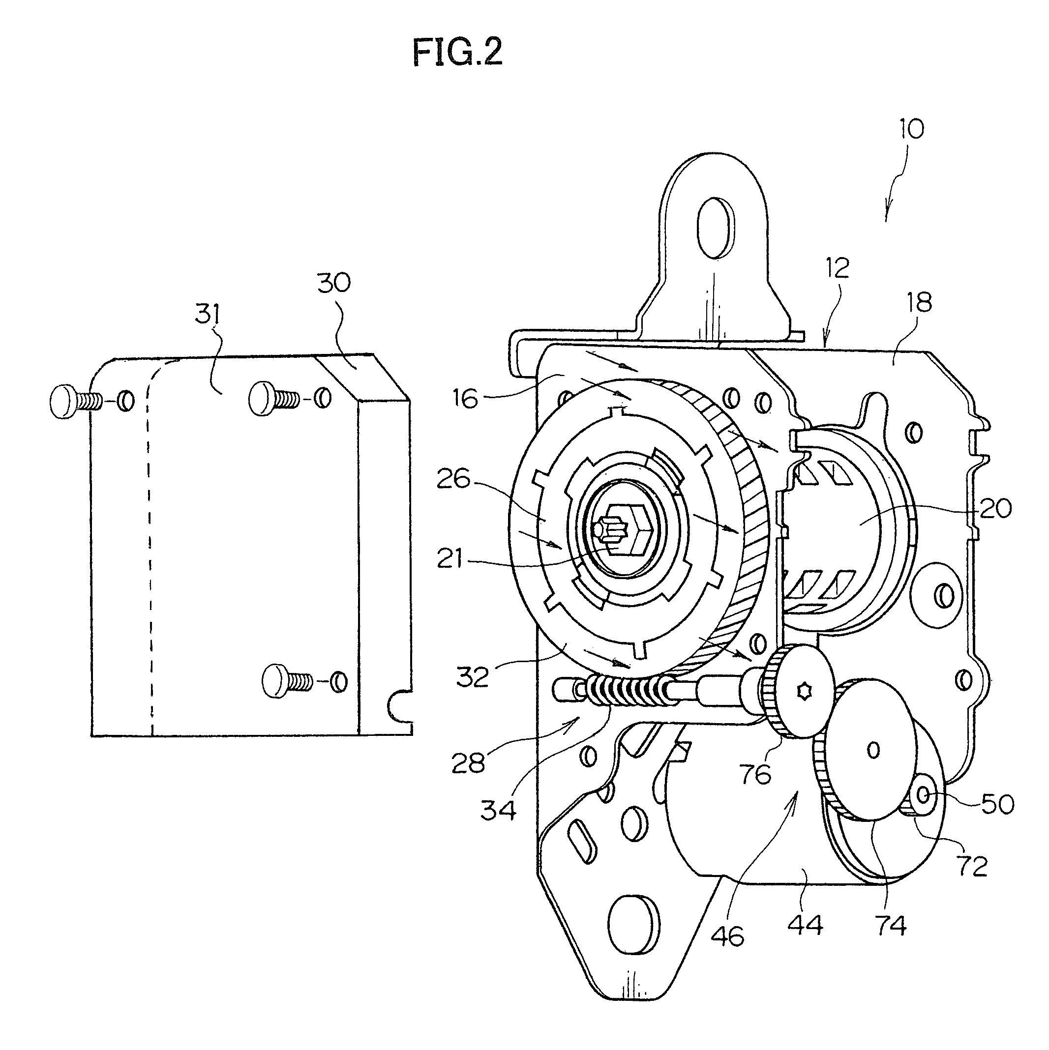
[0028]FIG. 1 is a perspective view showing the overall structure of a webbing take-up device 10 according to an embodiment of the present invention, and FIG. 2 is a perspective view showing the structure of the principal portion of the webbing take-up device 10. Further, FIG. 3 is an exploded perspective view showing the overall structure of the webbing take-up device 10.

[0029]The webbing take-up device 10 includes a frame 12. The frame 12 is formed by a substantially plate-shaped back plate 14, and a pair of leg plates 16 and 18 integrally extending from both transverse-direction ends of the back plate 14, respectively. The frame 12 is structured to be mounted to a vehicle body in such a manner that the back plate 14 is fixed to the vehicle body by means of unillustrated fastening means such as a bolt.

[0030]A take-up shaft 20 produced by die-casting or the like is rotatably disposed between the pair of leg plates 16 and 18 of the frame 12. The take-up shaft 20 is formed in an hourg...


PUM


Abstract

In a webbing take-up device 10, a worm gear 34, which is connected to a motor 44, engages with a gear wheel 32, and when the worm gear 34 rotates, driving force is transmitted via the gear wheel 32 and a clutch 26, whereby a take-up shaft 20 is rotated in a take-up direction. Helix angles of teeth of the worm gear 34 and the gear wheel 32 are set so that thrust force generated at this time along the axial direction of the gear wheel 32 faces a leg plate 16 fixed side of a case 30. Accordingly, because the thrust force acts on the leg plate 16 fixed side of the case 30, i.e., on a frame 12, there is no need to provide the case 30 or a cover clutch 31 with high strength and rigidity.

Description

TECHNICAL FIELD[0001]The present invention relates to a webbing take-up device, and particularly to a webbing take-up device that is capable of taking up a webbing due to a take-up shaft being rotated by a motor.BACKGROUND OF THE ART[0002]A seat belt apparatus for restraining a vehicle occupant is equipped with a webbing take-up device. Some webbing take-up devices have been proposed which each include a so-called tension reducer mechanism for mitigating or eliminating an excessive sensation of pressure that the vehicle occupant feels when a webbing is applied to the occupant, or a pretensioner mechanism that eliminates a slight looseness called “slack” or the like by taking up a webbing belt onto a take-up shaft by a certain amount at the time when a vehicle rapidly decelerates or the like and that increases a restraining force by which the webbing belt restrains the body of the vehicle occupant, thereby allowing the body of the vehicle occupant to be held more reliably. Further, t...

Claims


Application Information

Patent Timeline
Patent Type & Authority Patents(United States)
IPC IPC(8): B60R22/46B60R22/48B60R22/34B60R22/44
CPCB60R22/44B60R2022/4473B60R2022/3402B60Y2304/05F16H1/06
Inventor SAITO, TAKUHIROASAGIRI, KATSUKI
Owner KK TOKAI RIKA DENKI SEISAKUSHO
Why Eureka
Try Eureka