
Self-ligating orthodontic bracket

a self-ligating, orthodontic technology, applied in the field of self-ligating orthodontic brackets, can solve the problems of irritating the tissues of the mouth, imposing difficulty in opening and closing procedures, etc., and achieve the effect of efficient opening and closing and enhancing patient treatmen

Active Publication Date: 2011-10-04
TP ORTHODONTICS
View PDF16 Cites 18 Cited by
  • Summary
  • Abstract
  • Description
  • Claims
  • Application Information

AI Technical Summary

Benefits of technology

[0020]Further, the bracket of the present invention may be also configured to receive an elastomeric or metal ligature to assist in maintaining the jaws in closed position particularly when a bracket is mounted on a malrotated tooth. Once the tooth is rotated to its proper position, the ligature can be removed on the basis it is no longer needed.
[0021]It is therefore an object of the present invention to provide a new and improved self-ligating orthodontic bracket for use in the orthodontic treatment of patients that may be efficiently opened and closed by a professional user for insertion or removal of the main archwire during treatment to enhance the treatment of patients.
[0023]A further object of the present invention is to provide a new and improved self-ligating orthodontic bracket that will not only enhance the treatment of patients but also reduce the chair time for the professional user.

Problems solved by technology

Moreover, some heretofore known self-ligating brackets are burdened by complex mechanical configurations that have a tendency to excessively trap food particles, irritate the tissues of the mouth, and impose difficulty in opening and closing procedures.

Method used


Image

  • Self-ligating orthodontic bracket
  • Self-ligating orthodontic bracket
  • Self-ligating orthodontic bracket

Examples


Embodiment Construction

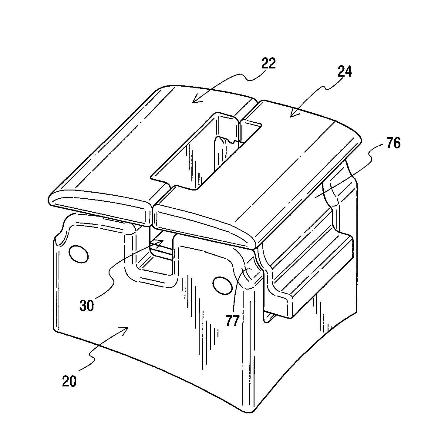
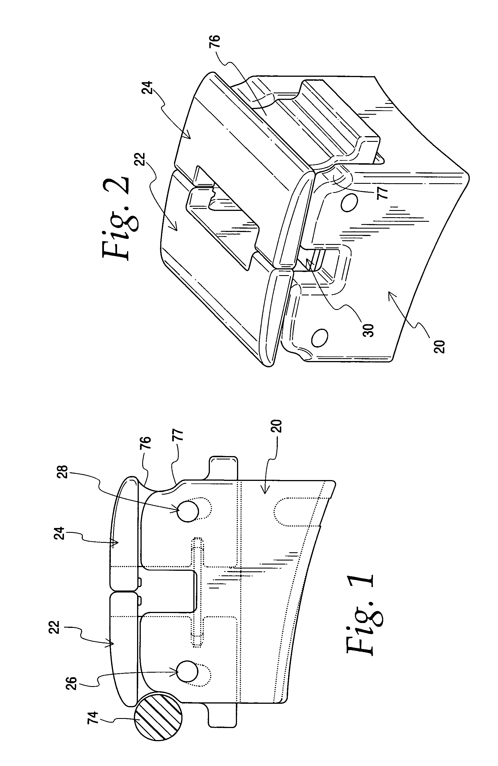
[0040]Referring now to the drawings, and particularly to the embodiment of FIGS. 1-11, for performing the edgewise technique, the bracket 18 includes in general a base 20, a pair of opposed jaw members 22 and 24, a pair of hinge pins 26 and 28, and a spring member 30.

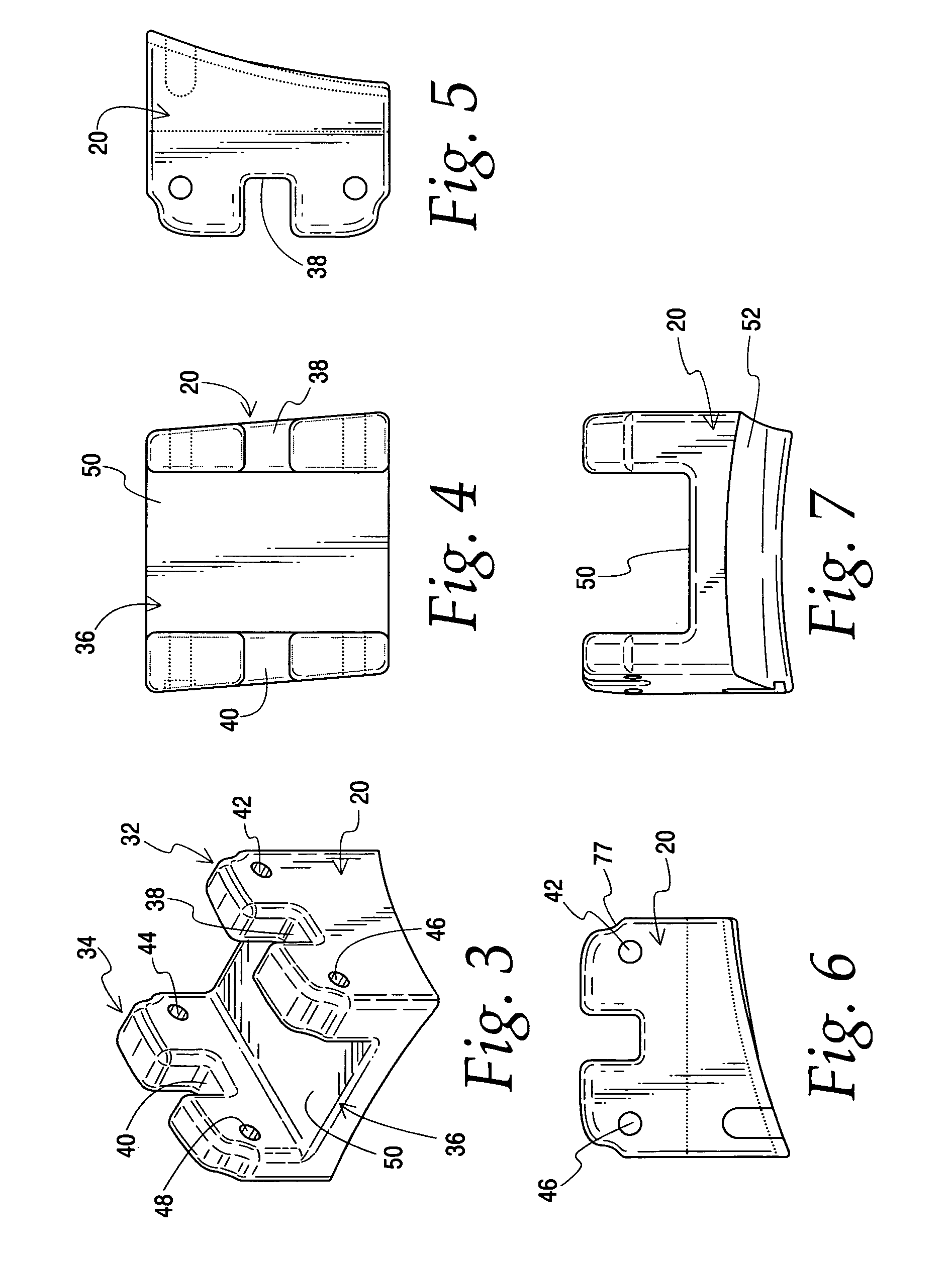
[0041]The base member includes a pair of substantially upstanding and substantially parallel hinge members 32 and 34 interconnected at their bottom end by a plate 36. While use of a solid plate is preferred because it defines the mounting face on the lingual of the bracket, it should be appreciated the plate may have openings, or bars may be used to interconnect the hinge members. The hinge members include aligned slots 38 and 40 that are U-shaped and configured to receive a main archwire and thereby coact to define an archwire slot for the bracket. The upstanding members 32 and 34 also include aligned bores 42 and 44 for receiving the hinge pin 28 and aligned bores 46 and 48 for receiving the hinge pin 26.

[0042]The jaw...


PUM


Abstract

A self-ligating orthodontic bracket including a base mountable on a tooth and having upstanding hinge members with aligned slots defining an archwire slot and for pivotally and slidably receiving a pair of openable and closable jaws and a spring member engaging said jaws and actuable upon opening and closing said jaws to selectively lock the jaws into open position for insertion or removal of an archwire and closed position for locking the archwire to the bracket.

Description

[0001]This invention relates in general to an orthodontic appliance for connecting an archwire to a tooth, and more particularly to a self-ligating orthodontic bracket mountable on a tooth that may be selectively opened for insertion or removal of an archwire or closed for retaining an archwire in the bracket, and still more particularly to a self-ligating orthodontic bracket having a pair of slidable and pivotally mounted jaws selectively locked in open or closed positions by a spring member.BACKGROUND OF THE INVENTION[0002]Heretofore, it has been well known to provide self-ligating orthodontic brackets for use in the orthodontic treatment of patients that eliminate the need to rely on ligatures for retaining an archwire in the archwire slot of the bracket. A self-ligating bracket is intended to enhance the efficiency of orthodontic treatment and to eliminate any problem encountered in ligature failure whether the ligature be elastomeric or wire in form.[0003]The orthodontic bracke...

Claims


Application Information

Patent Timeline
Patent Type & Authority Patents(United States)
IPC IPC(8): A61C3/00
CPCA61C7/303A61C7/287A61C7/285A61C7/30
Inventor KESLING, ANDREW C.
Owner TP ORTHODONTICS
Learn More