Reagent injection device

Active Publication Date: 2008-05-27
KATOH OSAMU +1
View PDF50 Cites 66 Cited by
  • Summary
  • Abstract
  • Description
  • Claims
  • Application Information

AI Technical Summary

Benefits of technology

[0018]Yet another preferred embodiment comprises a third lumen positioned inside of the main tube so that the center of the projection hole is preferably positioned in the plane that includes the center axes of the third lumen and the main tube. This configuration allows the needle tube to be preferably positioned inside of the main tube in a more balanced manner, thus allowing smoother performance of the applicable medical technique.
[0019]In an embodiment of the reagent injection device based on the present invention, it is advantageous to position the aforementioned third lumen inside of the main tube in so that its center axis corresponds to the center axis of the main tube. Moreover, the first and second lumens are positioned inside of the main tube, on both sides of the third lumen, in such a way that their center axes are positioned in the same plane that includes the center axis of the third lumen. This configuration preferably causes the distance between the first and second lumens to be maximized, thereby increasing the distance between the first and second guide wires extending out of the first and second lumens. Consequently, a majority of the reactive force generated as the needle progresses into the body tissue can be sufficiently and reliably supported by the first and second guide wires.
[0020]Another preferred embodiment of the present invention comprises an expandable and/or shrinkable balloon attached to the exterior of the main tube. The embodiment preferably comprises a fourth lumen, that supplies a liquid for expanding the balloon, positioned within the main tube so that the center of the aforementioned projection hole is positioned in the same plane that includes the center axes of the fourth lumen and main tube. In a reagent injection device comprising this configuration, the main tube can preferably be fixed in a specified position in the blood vessel into which the main tube is inserted. This is preferably achieved by expanding the balloon inside of the blood vessel. This allows the needle to project out of the main tube and pierce a desired location of body tissue in a more reliable manner. The fourth lumen that supplies the liquid for expanding the balloon can preferably be positioned inside of the main tube in a more balanced manner. As a result, the applicable medical technique using the reagent injection device can be performed more smoothly.
[0021]In preferred embodiments, a guide surface is provided in the main tube that guides the needle into the projection hole by means of the frictional contact created by the needle and the axial movement of the needle tube. The guide surface is preferably formed with a convex pattern that curves in the opening direction of the projection hole toward the front of the main tube, as viewed in the direction of its insertion into the body. This configuration allows for a smoother projection of the needle out of the main tube, thus enabling smoother performance of the applicable medical technique.
[0022]In further embodiments, the needle at the tip of the needle tube preferably comprises a curved shape corresponding to the convex guide surface as formed inside the main tube.

Problems solved by technology

However, conventional reagent injection devices are generally equipped with a long, flexible needle tube, which can become bent or retracted upon contact with the r

Method used


Image

  • Reagent injection device
  • Reagent injection device
  • Reagent injection device

Examples


Example

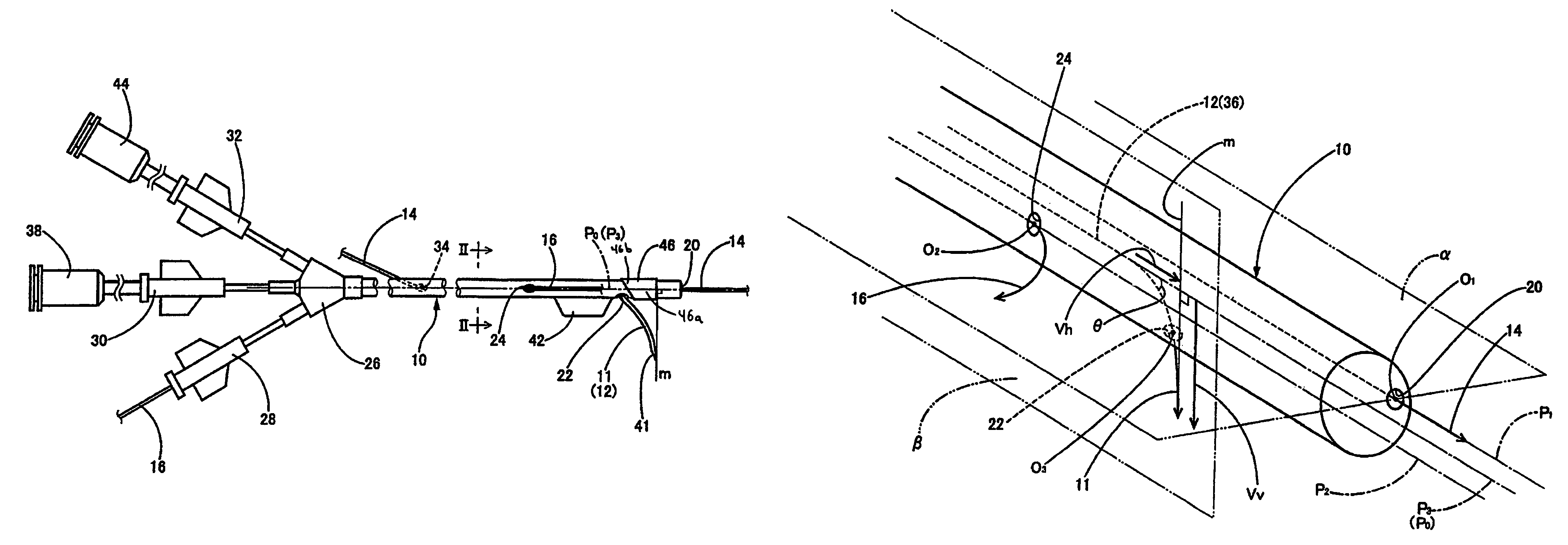
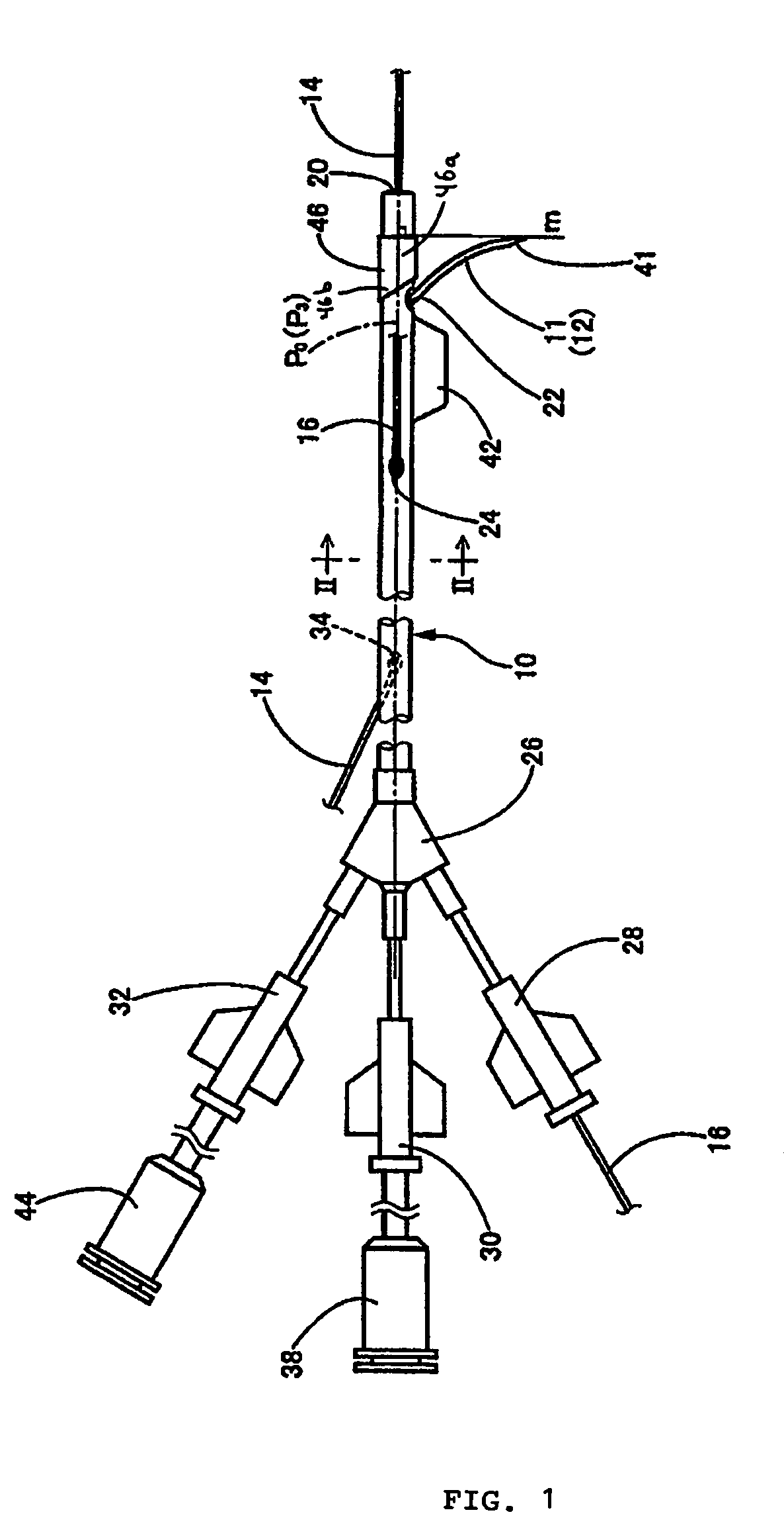
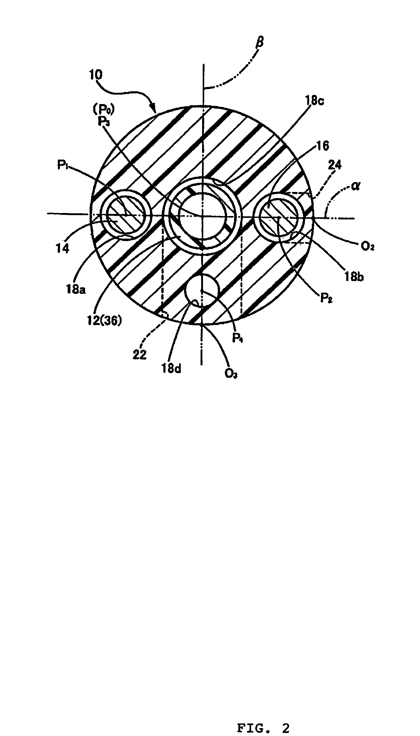
[0038]The structures of reagent injection devices embodied by the present invention are explained below in detail by referring to the drawings, in order to further elaborate on the present invention.

[0039]FIGS. 1 and 2 show a front and cross sectional view, respectively, of a preferred embodiment of a reagent injection device of the present invention. FIGS. 1 and 2, show a catheter body (10), or main tube, comprising a long tubular body. There is provided a needle tube (12) comprising a needle (11) at its tip, a first guide wire (14) and a second guide wire (16), each of which are inserted into the catheter body and movable in their respective axial directions.

[0040]The catheter body (10) preferably has a thickness (approximately 2.0 mm in diameter) and length that allows the catheter to be preferably inserted into the blood vessels extending from the thighs or wrists to the heart in the human body at any point over their entire lengths. The catheter body (10) preferably comprises f...


PUM


Abstract

Embodiments of the present invention relate to an injection devices that inject a specified reagent with cells into lesions and other areas of body tissue. Particular embodiments comprise a main tube with a projection hole on its exterior, an axially-moveable needle tube with a needle at its tip, a reagent supplier configured to supply a specified reagent into the needle tube, and axially-moveable guide wires.

Description

BACKGROUND OF THE INVENTION[0001]The present application claims priority under 35 U.S.C. § 119 to Japanese Patent Application No. 2003-059868, filed on Mar. 6, 2003, the disclosure of which is incorporated herein by reference in its entirety.[0002]1. Field of the Invention[0003]The present invention relates to reagent injection devices. More particularly, this invention relates to an injection device that injects a specified reagent (which need not but may contain cells, chemicals, etc.) into lesions and other areas of body tissue.[0004]2. Description of the Related Art[0005]In various medical procedures, catheters and other medical apparatuses have traditionally been inserted into components of the cardiovascular system, the gastrointestinal tract, the urinal tract, and other tubular organs of the human body. Recently, as illustrated in Japanese Patent Application Laid-open Nos. 2001-104487 and 2001-299927, reagent injection catheters have been used to inject specific reagents into...

Claims


Application Information

Patent Timeline
IPC IPC(8): A61M5/178A61M25/00A61M25/01
CPCA61M25/0084A61M2025/009
Inventor KATOH, OSAMUMOMOTA, MASASHIKATO, TOMIHISA
Owner KATOH OSAMU
Why Eureka
Try Eureka