Laundry treatment machine

Pending Publication Date: 2021-06-03
LG ELECTRONICS INC
View PDF2 Cites 0 Cited by
  • Summary
  • Abstract
  • Description
  • Claims
  • Application Information

AI Technical Summary

Benefits of technology

[0041]A laundry treatment machine according to an embodiment of the present disclosure includes a controller configured to start dewatering after a first period from completion of drainage when a lift is at a first level, and to start the dewatering after a second period from the completion of the drainage when the lift is at a second level greater than the first level, wherein the second period is longer than the first period, wherein the lift is a difference between a water level of the water introduction part through which water flows into the drain pump and a water level of a water discharge part through which the water is discharged out of the drain pump. In this way, it is possible to change the dewatering entry period after drainage is completed, based on the lift. In particular, it is possible to shorten the dewatering entry period after drainage is completed.
[0042]In the laundry treatment machine according to an embodiment of the present disclosure, the controller may be configured to perform the dewatering after the first period when the water level in the washing tub is equal to or less than a first water level and the lift is at the first level, during the drainage before the dewatering, and thus it is possible to shorten the dewatering entry period after the completion of the drainage.
[0043]In the laundry treatment machine according to an embodiment of the present disclosure, the controller may be configured to perform the dewatering after the first period when a level of the output current is equal to or less than a reference level, the water level in the washing tub is equal to or less than a first water level, and the lift is at the first level. Accordingly, the dewatering is performed based on the output current, and thus the dewatering entry period after the completion of the drainage can be shortened.
[0

Problems solved by technology

In this way, when the drain pump is operated at a constant speed by the input AC power, when the laundry treatment machine performs dewatering after the completion of the drainage, the motor driven in the constant speed operation is severely heated, and thus the motor for the drain

Method used


Image

  • Laundry treatment machine
  • Laundry treatment machine
  • Laundry treatment machine

Examples


Example

[0072]Reference will now be made in detail to the preferred embodiments of the present disclosure, examples of which are illustrated in the accompanying drawings. Wherever possible, the same reference numbers will be used throughout the drawings to refer to the same or like parts.

[0073]As used herein, the suffixes “module” and “unit” are added or used interchangeably to facilitate preparation of this specification and are not intended to suggest distinct meanings or functions. Accordingly, the terms “module” and “unit” may be used interchangeably.

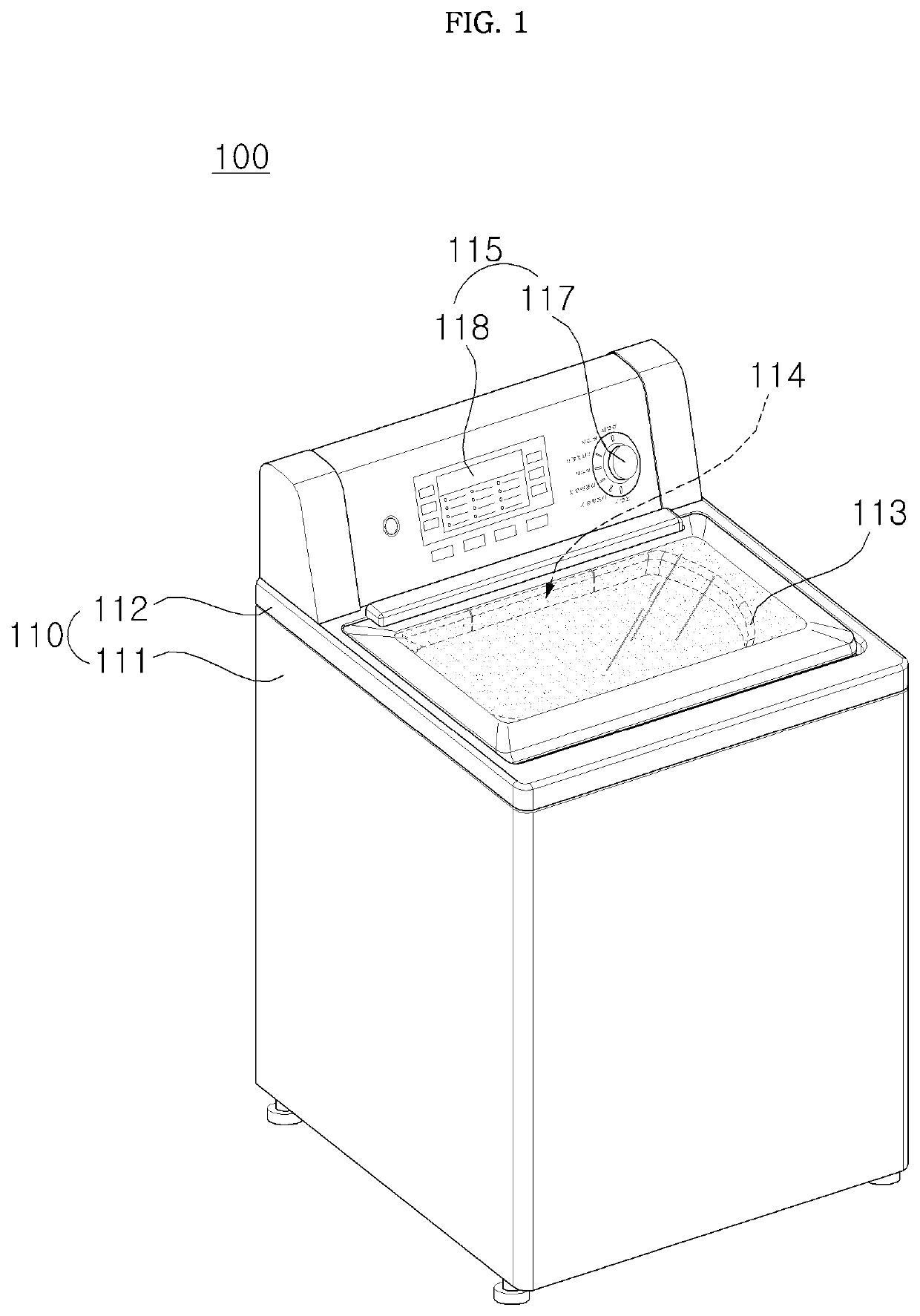
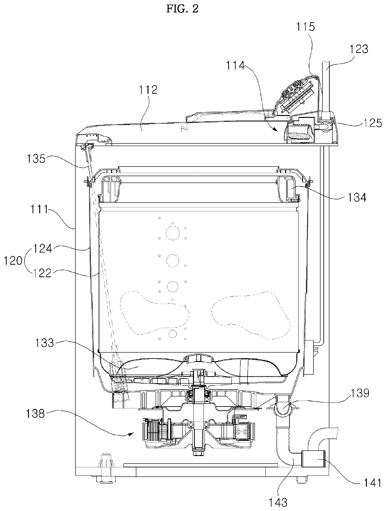
[0074]FIG. 1 is a perspective view illustrating a laundry treatment machine according to an embodiment of the present disclosure, and FIG. 2 is a side cross-sectional view illustrating the laundry treatment machine of FIG. 1.

[0075]Referring to FIGS. 1 and 2, the laundry treatment machine 100 according to an embodiment of the present disclosure conceptually includes a washing machine having fabric inserted therein for performing washing, rin...


PUM


Abstract

The present disclosure relates to a laundry treatment machine. The laundry treatment machine according to an embodiment of the present disclosure includes a controller configured to start dewatering after a first period from completion of drainage when a lift is at a first level, and to start the dewatering after a second period from the completion of the drainage when the lift is at a second level greater than the first level, wherein the second period is longer than the first period. Accordingly, based on the lift, it is possible to change the dewatering entry period after drainage is completed.

Description

BACKGROUND OF THE DISCLOSURE1. Field of the Disclosure[0001]The present disclosure relates to a laundry treatment machine, and more particularly, to a laundry treatment machine capable of changing a dewatering entry period after drainage is completed, based on a lift.[0002]In addition, the present disclosure relates to a laundry treatment machine capable of shortening a dewatering entry period after drainage is completed.[0003]In addition, the present disclosure relates to a laundry treatment machine capable of minimizing a decrease in drainage performance according to installation conditions.[0004]In addition, the present disclosure relates to a laundry treatment machine capable of shortening a drainage time.[0005]In addition, the present disclosure relates to a laundry treatment machine capable of being driven in a sensorless manner.2. Description of the Related Art[0006]A drain pump driving apparatus drives a motor during drainage to discharge water introduced into a water introd...

Claims


Application Information

Patent Timeline
IPC IPC(8): D06F39/08D06F33/42D06F33/34D06F33/47
CPCD06F39/087D06F33/42D06F2103/18D06F33/47D06F39/088D06F33/34D06F2105/08D06F2103/44D06F2105/48D06F33/40D06F2103/46D06F39/083D06F39/085D06F2105/10D06F39/08
Inventor JE, JUNGMOONLEE, KIWOOK
Owner LG ELECTRONICS INC
Why Eureka
Try Eureka