
Communication system between a vehicle network and a wayside network

Active Publication Date: 2012-04-17
SIEMENS MOBILITY SAS
View PDF15 Cites 1 Cited by
  • Summary
  • Abstract
  • Description
  • Claims
  • Application Information

AI Technical Summary

Benefits of technology

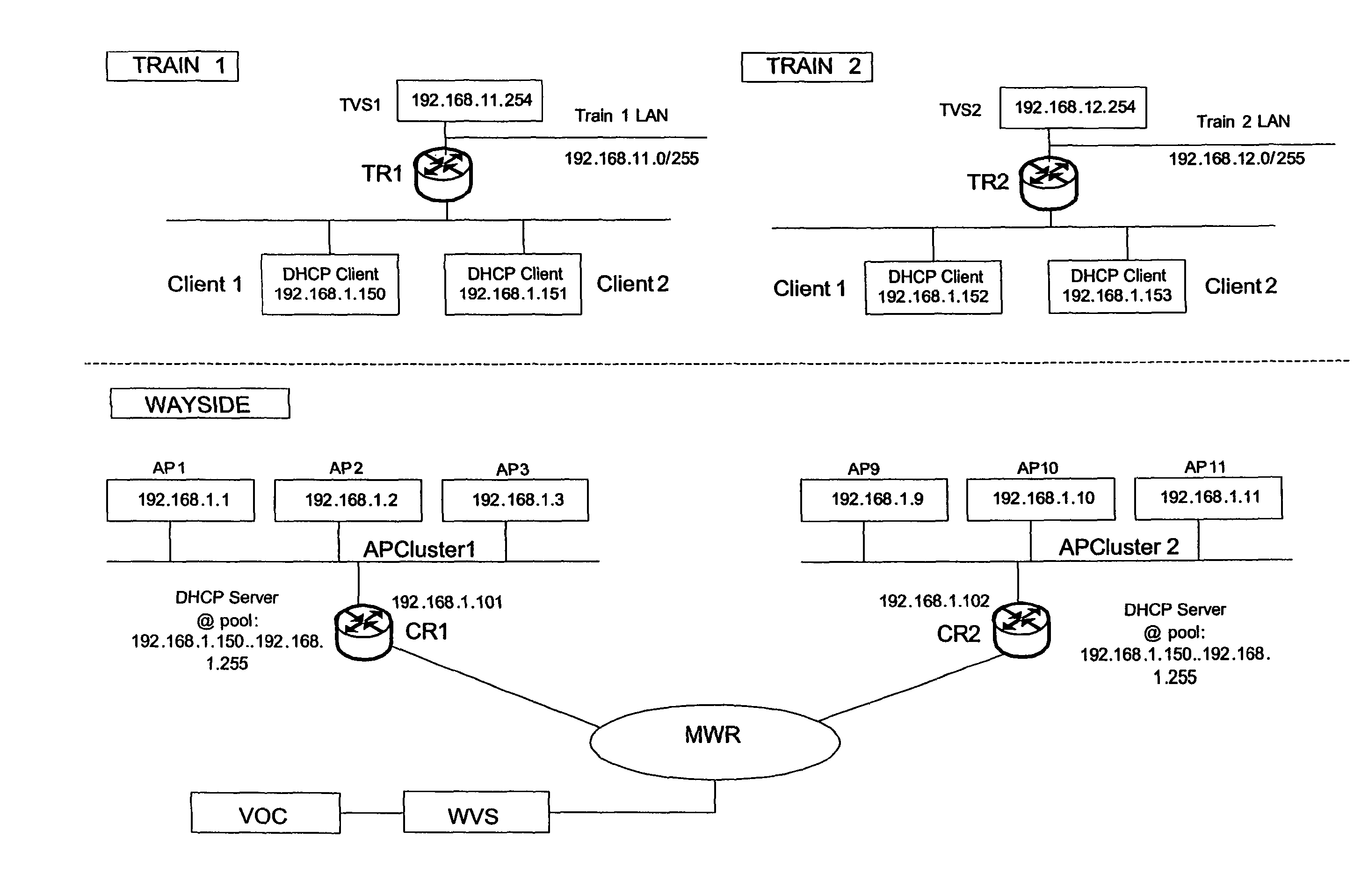
[0016]A further advantage of the invention consists in a clustered configuration of access points that are distributed in areas along the train rails. The radio frequency based connection of both clients is performed over distinctive access points that belong to the same or different clusters that are connected to the wayside network. A switch between two access points of a same cluster is hence permanently ensured. As well, a switch between two access points of two different clusters can be provided in real-time by means of a cluster router. A data re-routing by selecting a new client based gateway between the train and the wayside network doesn't depend anymore on roaming periods between clients and access points like in the described state-of-the-art, because switching processes are provided independently from usual slow clients roaming functions. All clients in the train are simultaneously connected to access points but only one is active for the data transmission. The switch period between them can also be considerably reduced by providing a switch at the wayside instead of the client side.
[0017]According to the wayside configuration, the access points are spatially arranged in a such way that a radio-frequency communication between two clients and the wayside network is permanently enabled over a single or two different clusters. By this way, a cluster dependent switch is also permanently enabled. If it is not the case, a means for storing temporary for example a train-outgoing data stream can be provided in the train network at least during the non-enabled communication.
[0018]The clusters are connected to a main wayside router of the wayside network over a cluster router and a data re-routing from a client in a train unit linked to a first cluster to a new selected client in the same or another train unit linked to a second cluster is provided by switching the cluster routers. In any way, the cluster routers are switched such that an in- or outgoing data streams are not interrupted.
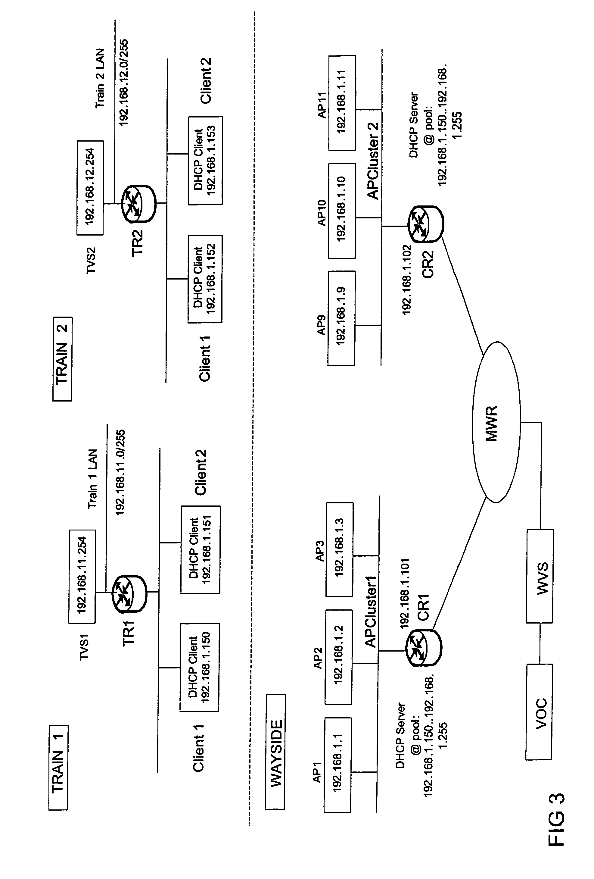
[0019]Generally the wayside network backbone is divided into several wayside subnets that can be linked to different clusters.
[0020]Advantageously, a data re-routing between a new selected client in the train and the main wayside router over different wayside clusters which are linked to different wayside subnets is performed by the main wayside router such that data are switched in real-time to the corresponding selected access point over the cluster router comprising the selected access point. This is possible because before or when a new client is physically selected, the train router forwards, in addition to the data traffic management from the train, the new routing scheme—new client, new access point / cluster—to the main wayside router. Hence, the main wayside router can permanently adapt the data routing over the subnets and the according clusters thanks to this updated association table.
[0021]At any time, the main wayside router comprises a routing address of the vehicle over the access point that is associated to selected client of train over the corresponding cluster router. This address is transmitted from the train router to the main wayside router in the frequently sent routing scheme. Therefore, the train router and the main wayside router are permanently informed on the routing scheme that should be used at any moment the train is moving. Once again, the routing scheme is transparent for the clients in the train, because after monitoring the best radio-frequency signal, only both train and main wayside routers manage the in- and outgoing data routing by permanently exchanging a preferred routing scheme according to a high quality radio-frequency criterion. The clients are only used as data gateway between train and main wayside routers, but their possible roaming means have not to be used.

Problems solved by technology

Unfortunately, the association and the roaming processes require a time period during which a communication of a data stream is not possible.

Method used


Image

  • Communication system between a vehicle network and a wayside network
  • Communication system between a vehicle network and a wayside network
  • Communication system between a vehicle network and a wayside network

Examples


Embodiment Construction

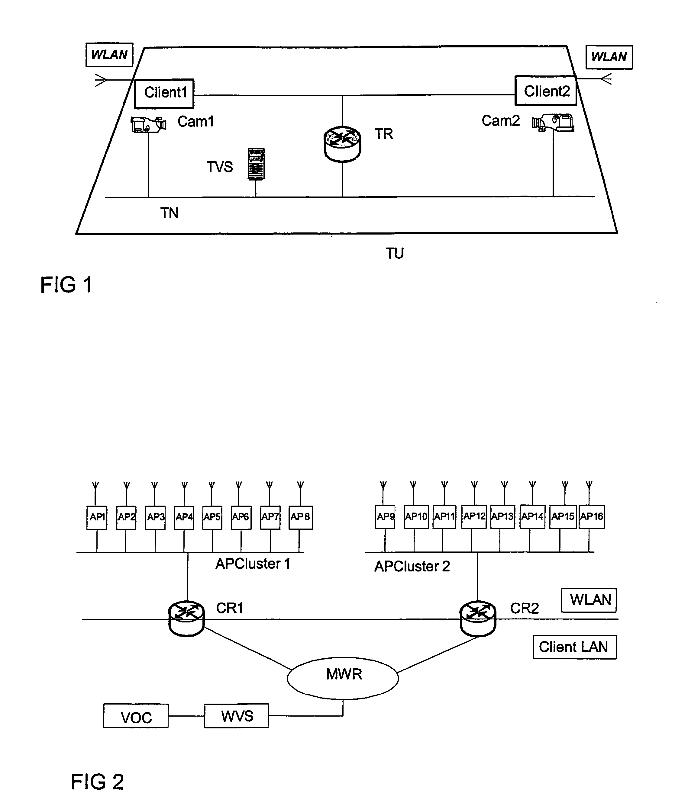
[0031]FIG. 1 is a schematic view of vehicle network architecture, for example for a train unit TU with a train network TN comprising a train router TR managing a data routing over one of at least two clients Client1, Client2 according to the invention. The monitoring means for measuring radio-frequency of the signal's quality from the clients can be integrated in the train router. The communication between the train network TN and a wayside network is provided by using one of the both clients Client1, Client2 as a gateway. In this example the communication is based on a WLAN radio-frequency connection (see the antenna of clients). For video monitoring application, two cameras Cam1, Cam2 are linked to the clients Client1, Client2 over the train network TN. Both cameras Cam1, Cam2 are generating video data streams that are re-directed over the selected client via the WLAN network to an access point at the wayside. A train video server TVS (or train unit video server) is also connected...


PUM


Abstract

A system for communications between a vehicle network and a wayside network includes a router in the vehicle network configured to manage routing of data over one of at least two clients, and a radio-frequency based communication network for providing a connection between each client and an access point linked to the wayside network. A monitoring device in a vehicle of the vehicle network is configured to control a quality of the connection in order to configure the router so that one of the clients is selected for the data routing between the vehicle and the wayside network.

Description

CROSS-REFERENCE TO RELATED APPLICATIONS[0001]The present application is a national stage application of International Application No. PCT / EP2006 / 004110, filed on May 3, 2006, which claims priority to European Application No. 05291105.4, filed on May 23, 2005, both of which are incorporated herein by reference.BACKGROUND OF THE INVENTION[0002]The present invention relates to a communication system between a vehicle network and a wayside network.[0003]According to the terminology “vehicle” the invention concerns especially rail train with one or more units in which a communication means between a trainborne network and a wayside network is provided.[0004]A first communication system is disclosed in WO200126337-A2 wherein a remote controlling of electronic components in vehicles through Internet as wayside network is provided for example for transmitting routing and security information for multimedia traffic through a device (GPS device, cellular phone, PDA, etc) connected over Wirele...

Claims


Application Information

Patent Timeline
IPC IPC(8): G06F15/173G06F15/16H04B1/26
CPCB61L27/0005B61L2205/02B61L27/70H04W24/00H04W40/34H04W84/12
Inventor DE LAJUDIE, RAPHAELLERENARD, NICOLASLOUDHAIEF, WISSAMRIVOALEN, MATHIEU
Owner SIEMENS MOBILITY SAS
Learn More