Control device for continuously variable transmission

Active Publication Date: 2015-03-05
JATCO LTD
View PDF1 Cites 0 Cited by
  • Summary
  • Abstract
  • Description
  • Claims
  • Application Information

AI Technical Summary

Benefits of technology

[0014](1) According to the control device for the continuously variable transmission, at the vehicle stop when the vehicle speed is 0, the Low-return control that operates the transmission ratio to the maximum transmission ratio with the frictional engagement element brought into the slip state which allows the transmission ratio of the continuously variable transmission mechanism to vary is performed. With this control, even when the vehicle stops by the hard braking, it is possible to operate the transmission ratio to the maximum transmission ratio, and also the power transmission to the drive wheel is not completely disconnected. Therefore, for instance, even in the case where the road where the vehicle stops is the uphill road, the slide-down (or the slip-down) of the vehicle can be suppressed. Further, since the frictional engagement element is in the slip state, the power transmission lag at the re-start can be suppressed, and there is no need to set the line pressure to be high.
[0015](2) In the case where the road where the vehicle stops is the upward slope (i.e. the uphill road), the engagement pressure of the frictional engagement element by which the frictional engagement element is brought into the slip state is set according to the estimated road slope, and the engagement pressure of the frictional engagement element is controlled so as to become this setting engagement pressure. It is therefore possible to operate the tr

Problems solved by technology

However, in a case of the deceleration by hard braking during vehicle travelling, since a time required for the vehicle stop is short, it is not possible to operate the transmission ratio up to the maximum transmission ratio by the time that the vehicle stops.
Further, if a wheel locks during the deceleration, even the operation to change the transmission ratio is not possible.
Also after the vehicle stop, it is not possible to operat

Method used


Image

  • Control device for continuously variable transmission
  • Control device for continuously variable transmission
  • Control device for continuously variable transmission

Examples


Example

[0025]In the following description, an embodiment of the present invention will be explained with reference to the drawings.

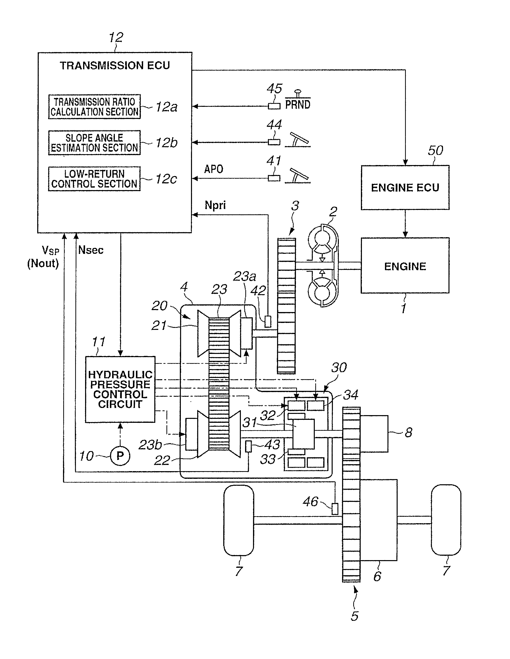
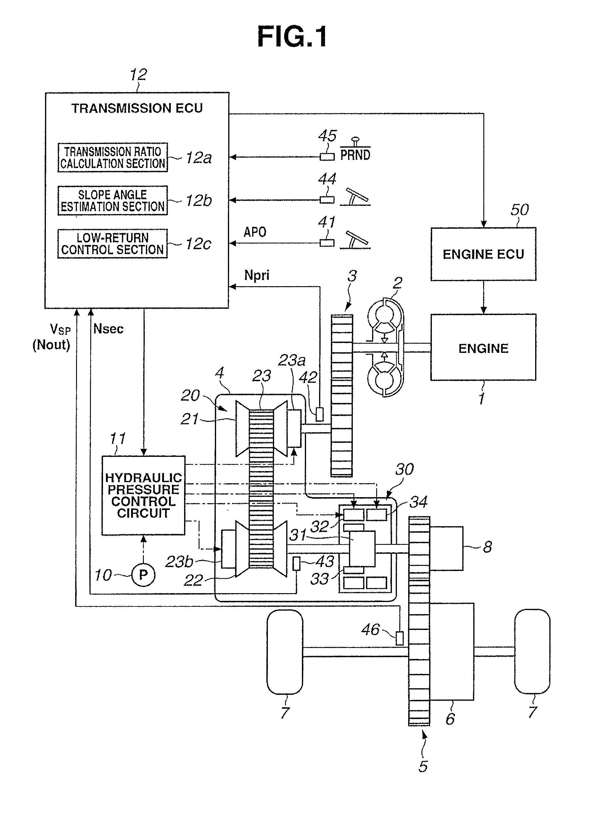
[0026]FIG. 1 is a block diagram of a driveline of a vehicle in which a continuously variable transmission and a control device of the continuously variable transmission according to the present embodiment are mounted. As shown in FIG. 1, this vehicle has an engine 1 as a power source. Output rotation of the engine 1 is transmitted to a drive wheel 7 through a torque converter 2 equipped with a lock-up clutch, a first gear train 3, the continuously variable transmission (hereinafter, also called simply a transmission) 4, a second gear train 5 and a final speed reduction device 6. The second gear train 5 is provided with a parking mechanism 8 that mechanically locks an output shaft of the transmission 4 so that the output shaft of the transmission 4 can not rotate upon parking.

[0027]Further, the vehicle has an oil pump 10 that is driven by using a part of the pow...


PUM


Abstract

A frictional engagement element (32) that disconnects power between an engine (1) and a drive wheel (7) in a vehicle, and a control unit (11, 12) that controls a transmission ratio of a continuously variable transmission (4) and the frictional engagement element (32), are provided. When the transmission ratio is not a maximum transmission ratio at a vehicle stop when a vehicle speed is 0, the control unit (11, 12) operates the transmission ratio to the maximum transmission ratio while controlling the frictional engagement element (32) into a slip state. Further, at this time, when a road is an upward slope, the control unit (11, 12) sets an engagement pressure of the frictional engagement element (32) and an engine torque according to the road slope, prevents slide-down of the vehicle.

Description

[0001]The present invention relates to a control device for a continuously variable transmission mounted in a vehicle.BACKGROUND ART[0002]In a vehicle having a continuously variable transmission, during deceleration before vehicle stop, by operating a transmission ratio up to a maximum transmission ratio by the time that the vehicle stops, starting performance at a subsequent re-start of the vehicle is ensured. However, in a case of the deceleration by hard braking during vehicle travelling, since a time required for the vehicle stop is short, it is not possible to operate the transmission ratio up to the maximum transmission ratio by the time that the vehicle stops. Further, if a wheel locks during the deceleration, even the operation to change the transmission ratio is not possible. Also after the vehicle stop, it is not possible to operate the transmission ratio as a matter of course.[0003]Patent Document 1 discloses that in a vehicle provided with an auxiliary transmission havin...

Claims


Application Information

Patent Timeline
IPC IPC(8): F16H61/662
CPCF16H2061/66209F16H61/66227F16H61/66259F16H61/702F16H2312/02F16H2061/6605F16H2059/663F16H2037/023
Inventor WOO, YOUNGJOOLIM, JONGKEUNCHOI, JUNSEOKPARK, CHANGNAMCHANG, MYONGSEOG
Owner JATCO LTD
Why Eureka
Try Eureka