Connector

Active Publication Date: 2018-10-25
SUMITOMO WIRING SYST LTD
View PDF1 Cites 0 Cited by
  • Summary
  • Abstract
  • Description
  • Claims
  • Application Information

AI Technical Summary

Benefits of technology

[0006]The forward inclination of the leg from the reference surface of the housing toward the arm ensures a smooth inclination displacement of the arm and achieves a small height of the connector. A releasing space is ensured between the releasing portion, the reference surface and the leg for allowing a releasing operation of the releasing portion is configured to release the locked state of the lock and the mating lock portion. However, this releasing space portion becomes wider by as much as the leg is inclined forward. Thus, the releasing operation can be performed smoothly.
[0007]A surface of the releasing portion substantially facing the ref

Problems solved by technology

However, if the projecting dimension of the leg is reduced, a height of a releasing space formed between the outer peripheral su

Method used


Image

  • Connector
  • Connector
  • Connector

Examples


Example

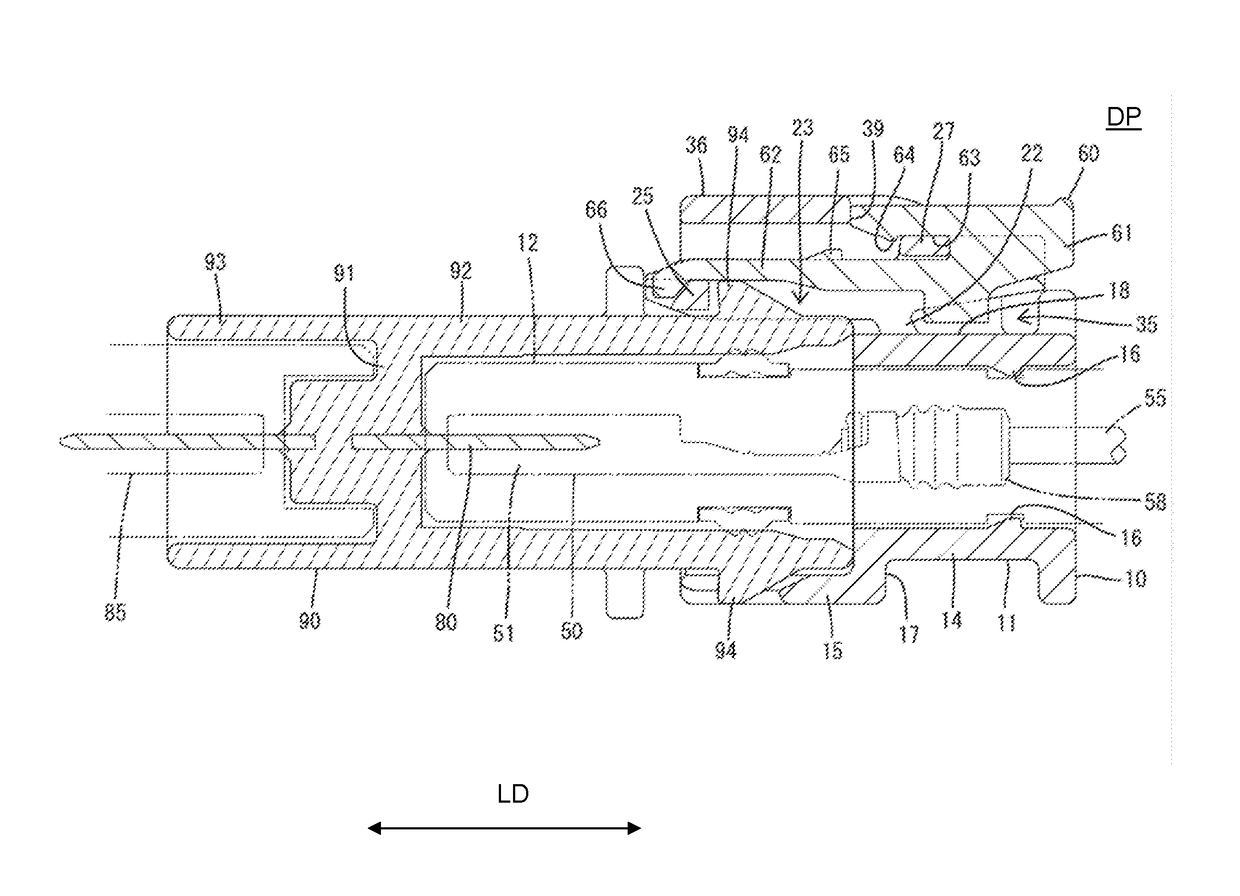
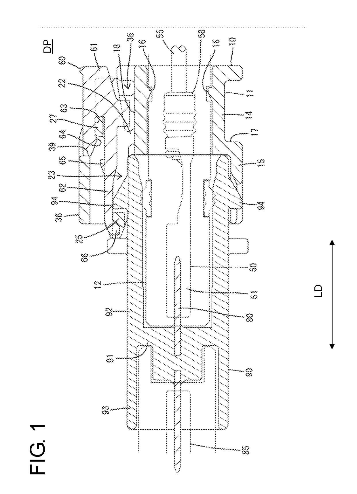
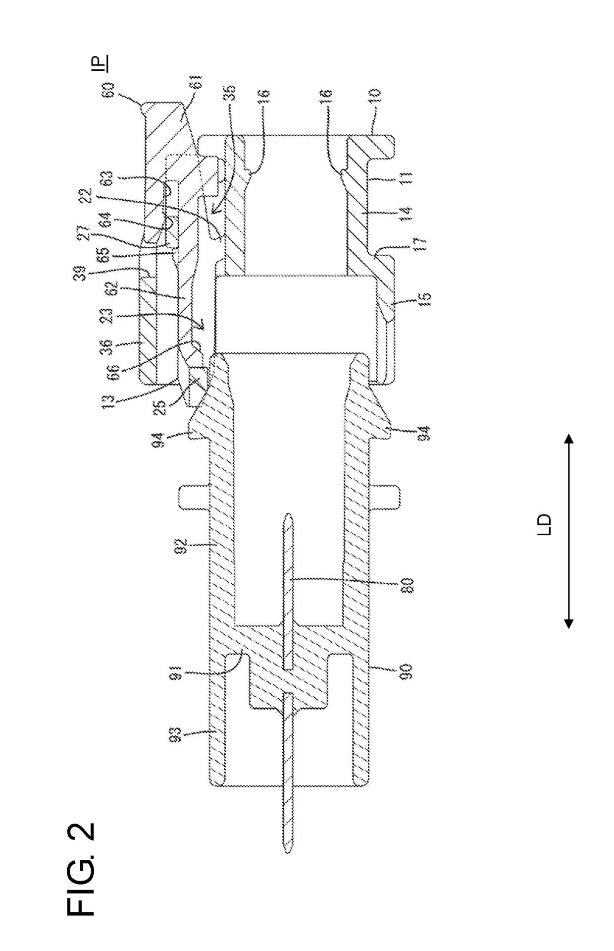
[0021]An embodiment of the invention is described with reference to FIGS. 1 to 6. A connector of this embodiment includes a housing 10 connectable to a mating housing 90 and a detector 60 assembled movably with the housing 10. Note that, in the following description, surfaces of the housings 10, 90 each other at the start of connection are referred to as fronts concerning a front-rear direction (or longitudinal direction LD), and a vertical direction is based on each figure except FIG. 5.

[0022]The mating housing 90 is made e.g. of synthetic resin and includes, as shown in FIGS. 1 and 2, a terminal mounting portion 91 in the form of a vertical wall extending substantially along the vertical direction (or a direction substantially normal to the longitudinal direction LD) and a receptacle 92 projecting forward from the terminal mounting portion 91. The receptacle 92 is formed into a flat tubular shape long in a lateral direction. Tab-like mating terminal fittings 80 extending in the fr...


PUM


Abstract

A connector includes a housing body (11) having a reference surface (18) extending substantially along a front-rear direction, an arm body (21) extending substantially along the front-rear direction, and legs (22) coupling an intermediate location of the arm body (21) in the front-rear direction and the reference surface (18). The area of the arm body (21) before the location coupled to the legs (22) is a lock (31) and the area behind the location coupled to the legs (22) is a releasing portion (32). The releasing portion (32) is pressed toward the reference surface (18), thereby releasing a locked state of the lock (31) and a mating lock (94). The legs (22) are inclined forward from the side of the reference surface (18) toward the side of the arm body (21).

Description

BACKGROUNDField of the Invention[0001]The present invention relates to a connector.Related Art[0002]Japanese Unexamined Patent Publication No. 2006-19187 discloses a connector with a male housing and a female housing connectable to each other. The female housing is provided with a lock arm extending in a front-rear direction along an outer peripheral surface. The lock arm is coupled to the outer peripheral surface of the female housing via a leg at an intermediate position in the front-rear direction. In the process of connecting the housings, the lock arm is pressed by a lock of the male housing to be inclined relative to a support. The lock arm resiliently returns when the housings are connected properly, and the lock of the male housing is fit into a lock hole provided in a front part of the lock arm to be locked. In this way, the housings are held in a connected state. On the other hand, if a releasing portion provided on a rear end part of the lock arm is pressed toward the out...

Claims


Application Information

Patent Timeline
IPC IPC(8): H01R13/436H01R13/627H01R13/641H01R13/52
CPCH01R13/4364H01R13/6271H01R13/641H01R13/5221H01R13/6272H01R13/633H01R2201/26H01R13/5219
Inventor IIDA, MASAHIRO
Owner SUMITOMO WIRING SYST LTD
Why Eureka
Try Eureka