Steerable conveyor

a conveyor and steerable technology, applied in the field of steerable conveyors, can solve the problems of difficult and awkward navigation of conveyors during transportation, longitudinally spaced wheels can be even more difficult to navigate during transportation, and the size of the typical conveyor is very limited, so as to achieve the effect of easy navigation

Active Publication Date: 2011-10-11
TOEWS BERNIE JOHN +3
View PDF19 Cites 15 Cited by
  • Summary
  • Abstract
  • Description
  • Claims
  • Application Information

AI Technical Summary

Benefits of technology

[0016]By providing a steering mechanism which commonly steers all of the wheels, each about their own axis, effective steering of an agricultural conveyor relative to a towing vehicle can be accomplished even when the conveyor is supported on two pairs of wheels such as a walking beam suspension for example. The controller allows the steering mechanism to control the path that the conveyor follows relative to the towing vehicle even when the conveyor wheels trails behind the towing vehicle by a considerable distance as in a larger screw auger or belt conveyors. The independent controller of the steering mechanism allows the conveyor to be readily navigated around various obstacles by also following a narrower or wider path than the towing vehicle if desired.

Problems solved by technology

Because of the large sizes of some conveyors, these conveyors can be very difficult and awkward to navigate during transport.
The longitudinally spaced wheels can be even more difficult to navigate during transport due to the wheels being restricted from pivoting in orientation relative to one another.
Auger moving kits are known, for example a self propelled auger transport kit available by Wheatheart, but such known systems are typically very limited in size and involve the costly addition of an auxiliary set of wheels supported on an auxiliary frame along with an additional motor suitable only for transport of smaller agricultural augers.
No means are provided for steering the conveyor relative to a vehicle during transport.
The steering mechanism in the form described is not readily adaptable to two pairs of wheels supported on a walking beam suspension as found on some larger agricultural conveyors.
None of the examples in the prior art are suitable for use on an agricultural conveyor for effectively steering the trailing movement of the conveyor relative to the towing vehicle.

Method used


Image

  • Steerable conveyor
  • Steerable conveyor
  • Steerable conveyor

Examples


Embodiment Construction

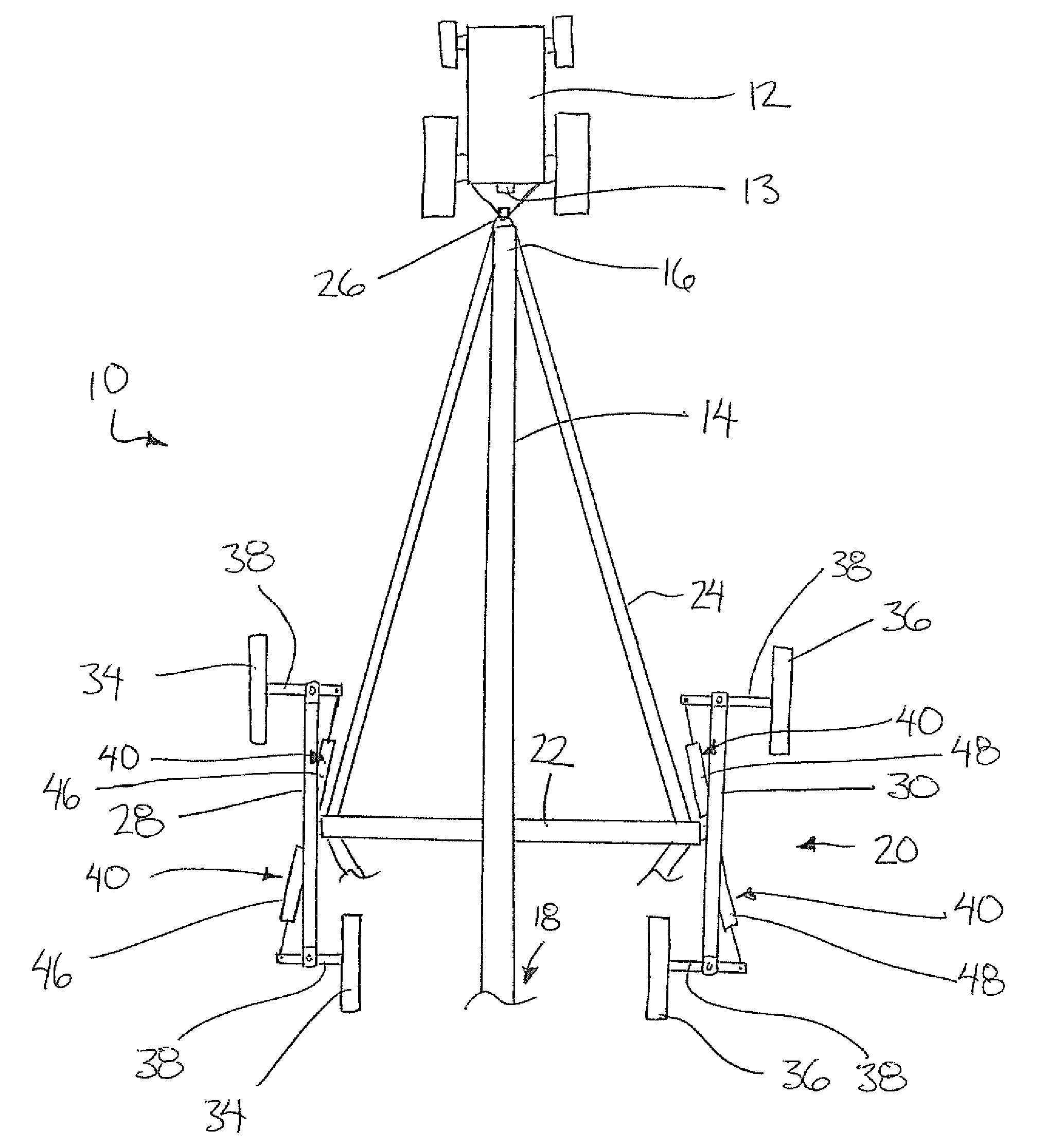
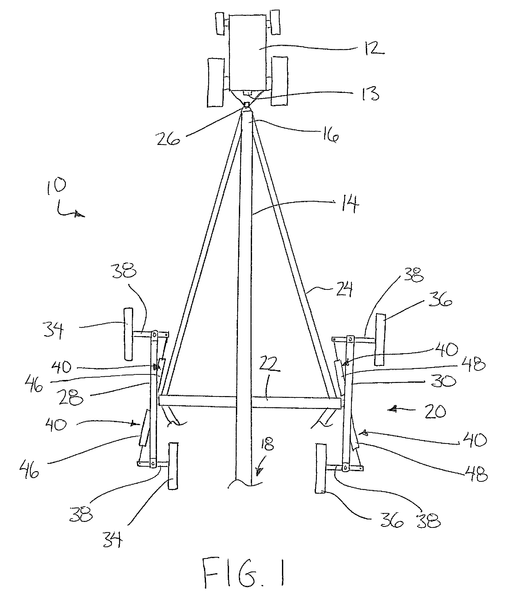
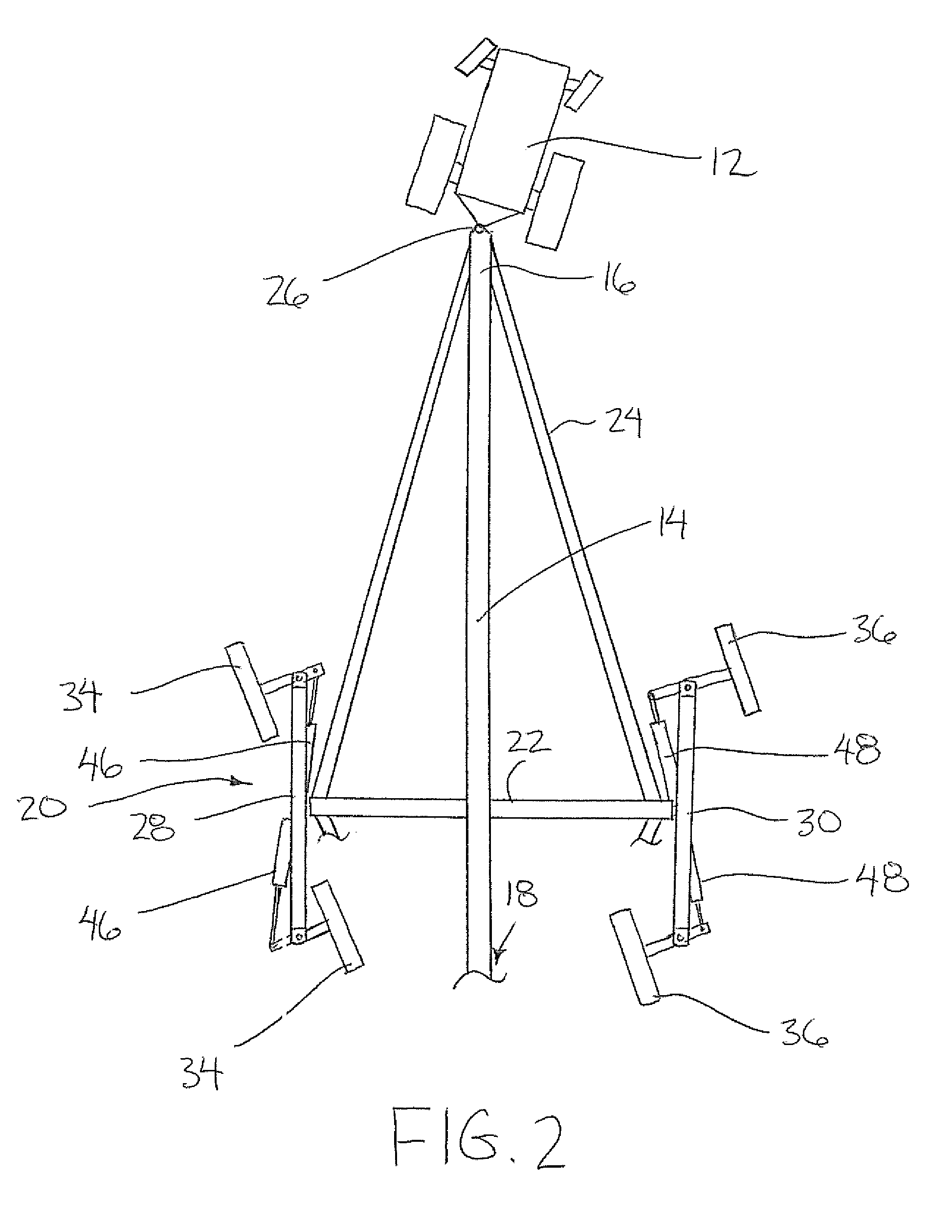
[0042]Referring to the accompanying figures there is illustrated a steerable conveyor generally indicated by reference numeral 10. The conveyor 10 typically comprises an agricultural conveyor, for example a large screw type auger conveyor or a belt conveyor.

[0043]The conveyor is typically transported by connection to a towing vehicle 12, for example an agricultural tractor, a highway truck, or other implement handling equipment supported on its own vehicle wheels for rolling movement along the ground in a forward working direction in normal use. The vehicle 12 is also steerable and movable in an opposing rearward direction as in most convention wheeled vehicles. In a preferred embodiment, the towing vehicle comprises a hydraulic output 13 which is controllable by an operator of the vehicle to control steering of the conveyor relative to the towing vehicle. The hydraulic output 13 is controllable independently of the vehicle steering control which controls steering of the vehicle whe...


PUM


Abstract

The steerable conveyor includes a conveyor frame supported on a first pair of wheels and a second pair of wheels at laterally opposed first and second sides of the conveyor. The conveyor includes a hitch for connection to a towing vehicle such that the conveyor is pivotal relative to the towing vehicle about a vertical steering axis. A steering mechanism is arranged to pivot all of the steerable wheels relative to the conveyor frame about respective upright steering axes in a common direction of rotation such that the conveyor is arranged to be steered relative to the towing vehicle about the vertical steering axis by steering the conveyor wheels relative to the conveyor frame when the conveyor is towed by the towing vehicle.

Description

[0001]This application is a continuation-in-part of U.S. patent application Ser. No. 12 / 327,032, filed Dec. 3, 2008, and claims foreign priority benefits from Canadian Patent Application 2,614,538, filed Dec. 10, 2007.FIELD OF THE INVENTION[0002]The present invention relates to an agricultural conveyor having wheels which are steerable relative to a frame of the conveyor such that the conveyor can be steered relative to a towing vehicle when towing the conveyor, and more particularly the present invention relates to a steering mechanism for commonly steering the wheels of the conveyor when the conveyor is supported on two laterally opposed pairs of wheels.BACKGROUND[0003]Conveyors, and more particularly auger type screw conveyors, are available in relatively large sizes for agricultural applications. Conveyors of this type typically include a tubular housing supported on wheels which are parallel and spaced apart from one another on opposing sides of the housing and fixed in orienta...

Claims


Application Information

Patent Timeline
Patent Type & Authority Patents(United States)
IPC IPC(8): B65G41/00
CPCA01D75/008B62D13/005B62D13/04
Inventor TOEWS, BERNIE JOHNTOEWS, DEAN BERNIETOEWS, DEVIN JOHNTOEWS, DARREN BRYCE
Owner TOEWS BERNIE JOHN
Why Eureka
Try Eureka