Apparatus for analysis and control of a reciprocating pump system by determination of a pump card

a technology of reciprocating pump system and apparatus, which is applied in the direction of seismology for waterlogging, positive displacement liquid engine, instruments, etc., can solve the problems of complex apparatus and procedures, frequent inability to diagnose downhole pump conditions solely on the basis of visual interpretation, and expensive and cumbersome instruments

Active Publication Date: 2011-10-11
RAVDOS HLDG INC
View PDF6 Cites 52 Cited by
  • Summary
  • Abstract
  • Description
  • Claims
  • Application Information

AI Technical Summary

Problems solved by technology

Hopefully the downhole conditions can be deduced by visual inspection of the polished rod card or “surface card.” Owing to the diversity of card shapes, however, it was frequently impossible to make a diagnosis of downhole pump conditions solely on the basis of visual interpretation.
As a result it was frequently necessary to use complicated apparatus and procedures to directly take downhole measurements in order to accurately determine the performance characteristics at various depth levels within the well.
Because the sucker rod had to be pulled to record the pump cards, the instrument was costly and cumbersome to use.
In reality, damping in a sucker rod system is a complicated mixture of many effects.
Any error in the friction law will cause error in the computed pump card.
Friction causes a loss in pump stroke and as a result decreases lifting capacity.
Also it causes wear and tear on rods and tubing.
The practice of including deviation clauses in drilling contracts and the technology of measuring borehole path came about because of scandals in the oil industry.
Unscrupulous oil producers were intentionally draining oil reserves owned by neighboring leaseholders using slanted wells.
Deviated wells can diminish unwanted traffic in residential areas because only the surface locations need be serviced.

Method used


Image

  • Apparatus for analysis and control of a reciprocating pump system by determination of a pump card
  • Apparatus for analysis and control of a reciprocating pump system by determination of a pump card
  • Apparatus for analysis and control of a reciprocating pump system by determination of a pump card

Examples


Embodiment Construction

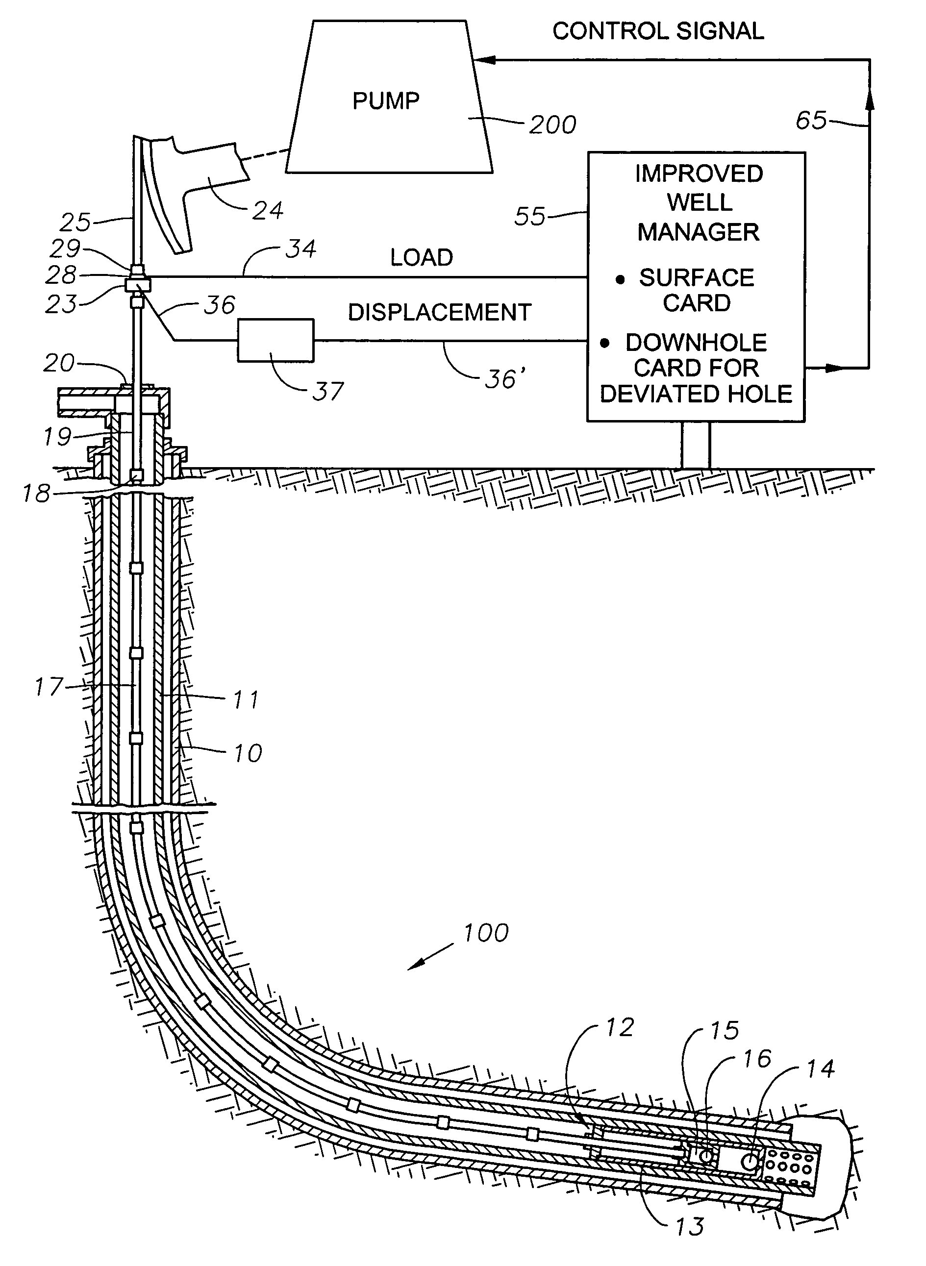
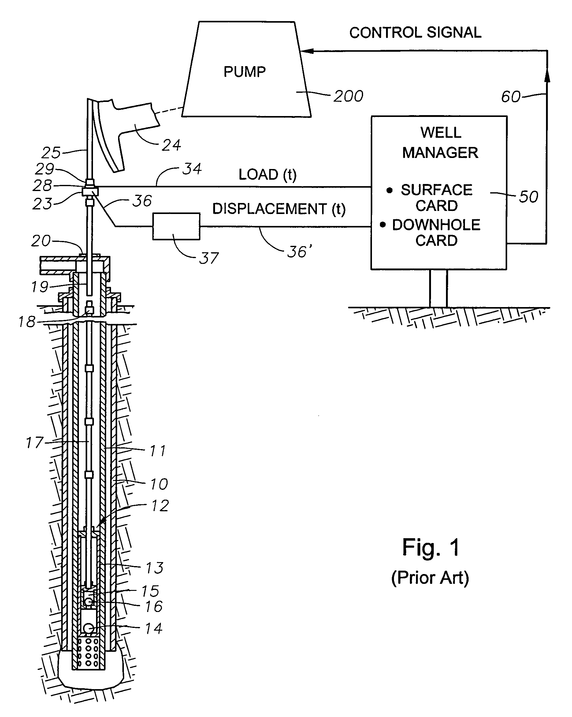
[0065]FIG. 4 illustrates a sucker rod pump operating in a deviated hole 100. The reference numbers for the casing, pump, sucker rods, etc. of FIG. 4 are the same as for the illustration of FIG. 1 for a vertical hole, but load signals 34 and displacement signals 36′ are applied (either by hardwire or wireless) to an Improved Well manager 55 for determination of a surface card and a downhole card for the deviated hole 100. A control signal 65 is generated in the improved well manager 55 and applied to the pump 200, by hardwire or wireless.

[0066]A deviated well like that of FIG. 4 requires a different version of the wave equation which models the more complicated rod on tubing drag forces,

[0067]∂ 2⁢u⁡(x,t)∂tt=v2⁢∂ 2⁢u⁡(x,t)∂x2-c⁢∂u⁡(x,t)∂t-C⁡(x)+g⁡(x)⁢⁢in⁢⁢which(8)C⁡(x)=δ⁢⁢μ⁡(x)⁡[Q⁡(x)+T⁡(x)⁢∂u⁡(x,t)∂x](9)δ=∂u⁡(x,t) / ∂t∂u⁡(x,t) / ∂t(10)

[0068]where[0069]v=velocity of sound in steel in feet / second;[0070]c=damping coefficient, 1 / second;[0071]t=time in seconds;[0072]x=distance of a point on t...


PUM


Abstract

An instrumentation system for assessing operation of a reciprocating pump system which produces hydrocarbons from a non-vertical or a vertical wellbore. The instrumentation system periodically produces a downhole pump card as a function of a directly or indirectly measured surface card and a friction law function from a wave equation which describes the linear vibrations in a long slender rod. A control signal or command signal is generated based on characteristics of the downhole pump card for controlling the pumping system. It also generates a pump and well analysis report that is useful for a pump operation and determination of its condition.

Description

BACKGROUND OF THE INVENTION[0001](1) Field of the Invention[0002]This invention relates to apparatus which determines the performance characteristics of a pumping well. More particularly, the invention is directed to apparatus for determining downhole conditions of a sucker rod pump in a vertical borehole or deviated borehole from data which are received, measured and manipulated at the surface of the well. The invention also concerns the analysis of pumping problems in the operation of sucker rod pump systems in such boreholes. A vertical borehole is one that is substantially vertical into the earth, but a deviated borehole is one that is non-vertical into the earth from the surface. A deviated borehole may be a horizontal borehole which extends from a vertical portion thereof.[0003]Still more particularly, the invention concerns improved a controller for analysis of downhole pump performance of a deviated borehole over the methods described in prior methods developed for nominally...

Claims


Application Information

Patent Timeline
Patent Type & Authority Patents(United States)
IPC IPC(8): G01V1/40G06F17/40
CPCF04B49/065E21B47/009
Inventor GIBBS, SAM G.DORADO, DONEIL M.NOLEN, KENNETH B.OESTREICH, ERIC S.DACUNHA, JEFFREY J.
Owner RAVDOS HLDG INC
Why Eureka
Try Eureka