Software executing device and co-operation method

a software and executing device technology, applied in the direction of instruments, analogue processes for specific applications, electric/magnetic computing, etc., can solve the problems of simulator general-purpose properties poor, simulation accuracy is reduced, simulation speed is affected,

Inactive Publication Date: 2011-10-11
KK TOSHIBA
View PDF16 Cites 7 Cited by
  • Summary
  • Abstract
  • Description
  • Claims
  • Application Information

AI Technical Summary

Problems solved by technology

Thus, there is such a problem that a decrease in a simulation speed is caused.
Since it is difficult to accurately handle a time of occurrence of an event (an interrupt request or the like) from the hardware side, there is such a problem that simulation accuracy is reduced.
Thus, the simulator has poor general-purpose properties.
Also, a mechanism for simulating the specifications of the “interrupt controller” which differ in each SoC means that an interrupt controller model for simulation is created, and the same problem as that in creating the HW model for simulation described above could be caused.

Method used


Image

  • Software executing device and co-operation method
  • Software executing device and co-operation method
  • Software executing device and co-operation method

Examples


first embodiment

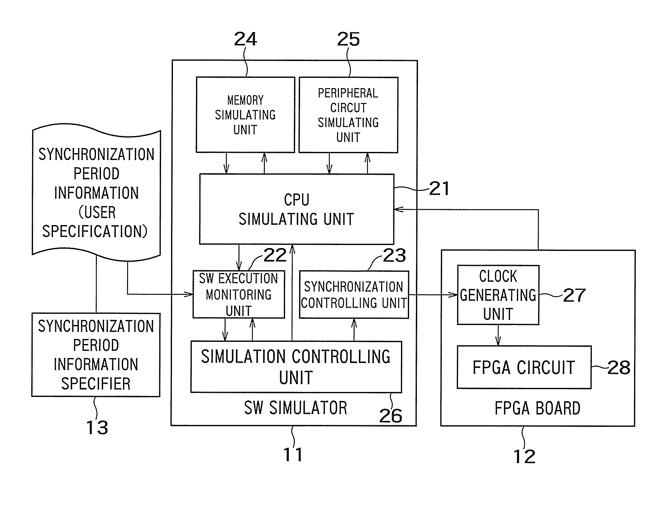
[0054]FIG. 1 is a block diagram illustrating an entire configuration of a hardware / software (HW / SW) co-simulator including a software simulator (SW simulator) 11 according to a first embodiment of the present invention. The SW simulator 11 shown in the drawing illustrates by blocks various functions obtained by executing a simulation program for achieving the present invention on a general-purpose computer. A device on which the simulation program is mounted corresponds to one embodiment of a software executing device according to the present invention.

[0055]The HW / SW co-simulator performs verification of software executed on a CPU simulating unit 21 in the SW simulator 11 by co-simulation of the SW simulator 11 and an FPGA board (hardware circuit) 12.

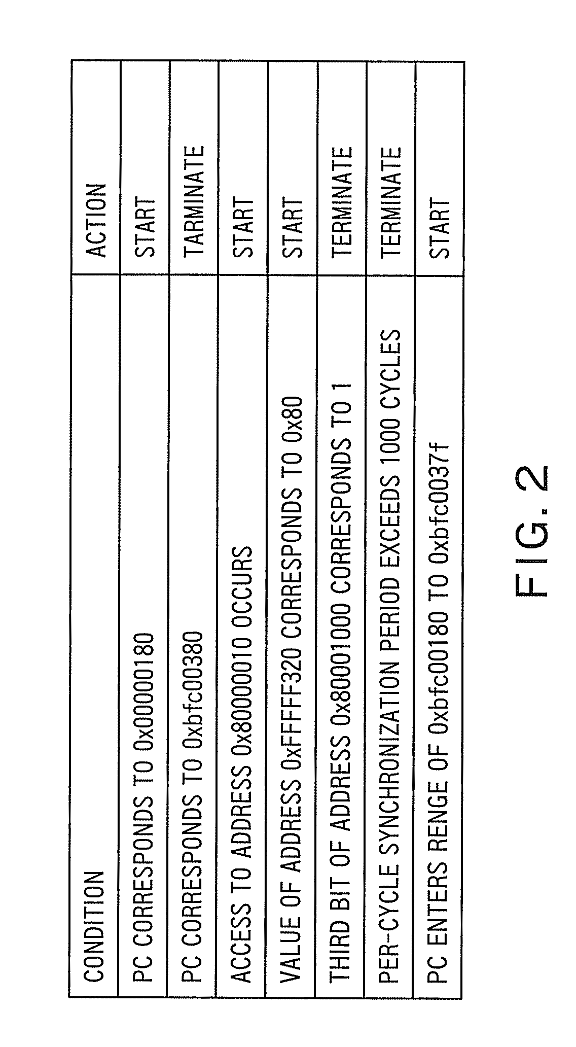
[0056]A synchronization period information specifier 13 shown in FIG. 1 is a program having a text editor or a dedicated graphical user interface (GUI), and a user specifies a start condition and a termination condition of the period i...

second embodiment

[0093]Although the example in which the co-simulation of the SW simulator and the FPGA board is performed is described in the first embodiment, the technique which is fundamental to the present invention is not limited to such combinations described in the first embodiment. A second embodiment shows an example of co-simulation by combining the SW simulator and an HW simulator.

[0094]FIG. 12 is a block diagram illustrating an entire configuration of an HW / SW co-simulator according to the second embodiment of the present invention. The elements having the same names as those in FIG. 1 are assigned the same reference numerals, and descriptions thereof are omitted since operations thereof are the same as those of the corresponding elements in FIG. 1. In specific, the operations in the SW simulator 11 side are equal to those in the first embodiment.

[0095]An HW simulator 51 performs simulation of hardware by using a hardware description (an RTL description or the like of target hardware) 5...

third embodiment

[0099]FIG. 14 illustrates an example in which an evaluation board 61 on which a real CPU is mounted and an in circuit emulator (ICE) 62 are used for the operations in the software side according to a third embodiment of the present invention. Combination of the evaluation board and the ICE 62 corresponds to the software executing device. The elements having the same names as those in FIG. 1 are assigned the same reference numerals to omit redundant descriptions. An execution controlling unit 63 in the ICE 62 has functions equal to those of the simulation controlling unit 26 in FIG. 1. By using the ICE or the like, information of an operation state (a program counter value, an address of bus access, a memory / register value) of software operating on the real CPU can be referenced. Here, the information of the operation state of the software can be obtained by the PC monitoring unit, the address monitoring unit, and the memory / register value monitoring unit included in the SW execution...


PUM


Abstract

There is provided with a software executing device co-operating with a hardware circuit or a hardware simulator, including: a software executing unit configured to execute a software; an execution monitoring unit configured to monitor execution of the software by the software executing unit to sequentially obtain an execution state of the software; a determining unit configured to determine whether the software executing unit and the hardware circuit or the hardware simulator are to be synchronized based on an obtained execution state of the software; and a synchronization controlling unit configured to control synchronization between the software executing unit and the hardware circuit or the hardware simulator.

Description

CROSS REFERENCE TO RELATED APPLICATIONS[0001]This application is based upon and claims the benefit of priority from the prior Japanese Patent Applications No. 2007-163652, filed on Jun. 21, 2007; the entire contents of which are incorporated herein by reference.BACKGROUND OF THE INVENTION[0002]1. Field of the Invention[0003]The present invention relates to a software executing device and a co-operation method, which are used, for example, in a hardware / software co-simulation environment.[0004]2. Related Art[0005]Hardware / software co-simulation (HW / SW co-simulation) is used to shorten time to market (TTM) for a system on chip (SoC) by starting verification of software / firmware (SW / FW) using HW simulation before the SoC is completed, or to reduce production man-hours of a test vector for verification by giving a test input to an HW description which is an object of verification, from a central processing unit (CPU) model of an SW simulation environment.[0006]In order to start the veri...

Claims


Application Information

Patent Timeline
Patent Type & Authority Patents(United States)
IPC IPC(8): G06F9/445G06F17/50
CPCG06F17/5022G06F30/33
Inventor IGARASHI, MASATO
Owner KK TOSHIBA
Why Eureka
Try Eureka