Liquid droplet jetting head

a jetting head and liquid drop technology, applied in printing and other directions, can solve the problems of large head size, inability to reach all the nozzles,

Active Publication Date: 2011-10-18
BROTHER KOGYO KK
View PDF4 Cites 4 Cited by
  • Summary
  • Abstract
  • Description
  • Claims
  • Application Information

AI Technical Summary

Benefits of technology

[0018]According to the first aspect of the present invention, the two pressure chamber groups are arranged in a row such that the space between the first pressure chamber included in the first pressure chamber group, which is positioned nearest to the second pressure chamber group, and a second pressure chamber included in the second pressure chamber group which is positioned nearest to the first pressure chamber group is larger than the first interval, and the auxiliary supply passage which supplies the ink to each common liquid chamber through the space is formed. Therefore, it is possible to supply a liquid such as ink even from a half-way portion of each common liquid chamber through the auxiliary supply passage. Accordingly, even in a head including a large number of nozzles in which the nozzle row is elongated, it possible to deliver sufficiently a liquid such as ink to all the nozzles.
[0022]In this case, a change in a volume of the first pressure chamber and the second pressure chamber adjacent to the sub ink supply tank, and a change in a volume of the other pressure chambers become equal, and it is possible to achieve uniform jetting performance.
[0029]In this case, it is possible to avoid interference between the sub supply passage and the flexible wire.
[0031]In this case, it is possible to avoid interference between the sub supply passage and the plurality of wires formed inside the piezoelectric actuator.
[0042]As it has been described above, according to the present invention, since it is possible to supply the ink from the half-way portion of the common liquid chamber through the auxiliary supply passage, it is possible to deliver sufficiently a liquid such as ink to all the nozzles without making large (without an increase in) a size of the liquid droplet jetting head.

Problems solved by technology

In this case, since the ink supply channel is formed at the end portion of the common liquid chamber, a problem that the ink can not reach all the nozzles may arise.
However, when the width of the common liquid chamber is widened, a size of the head becomes large.

Method used


Image

  • Liquid droplet jetting head
  • Liquid droplet jetting head
  • Liquid droplet jetting head

Examples


first embodiment

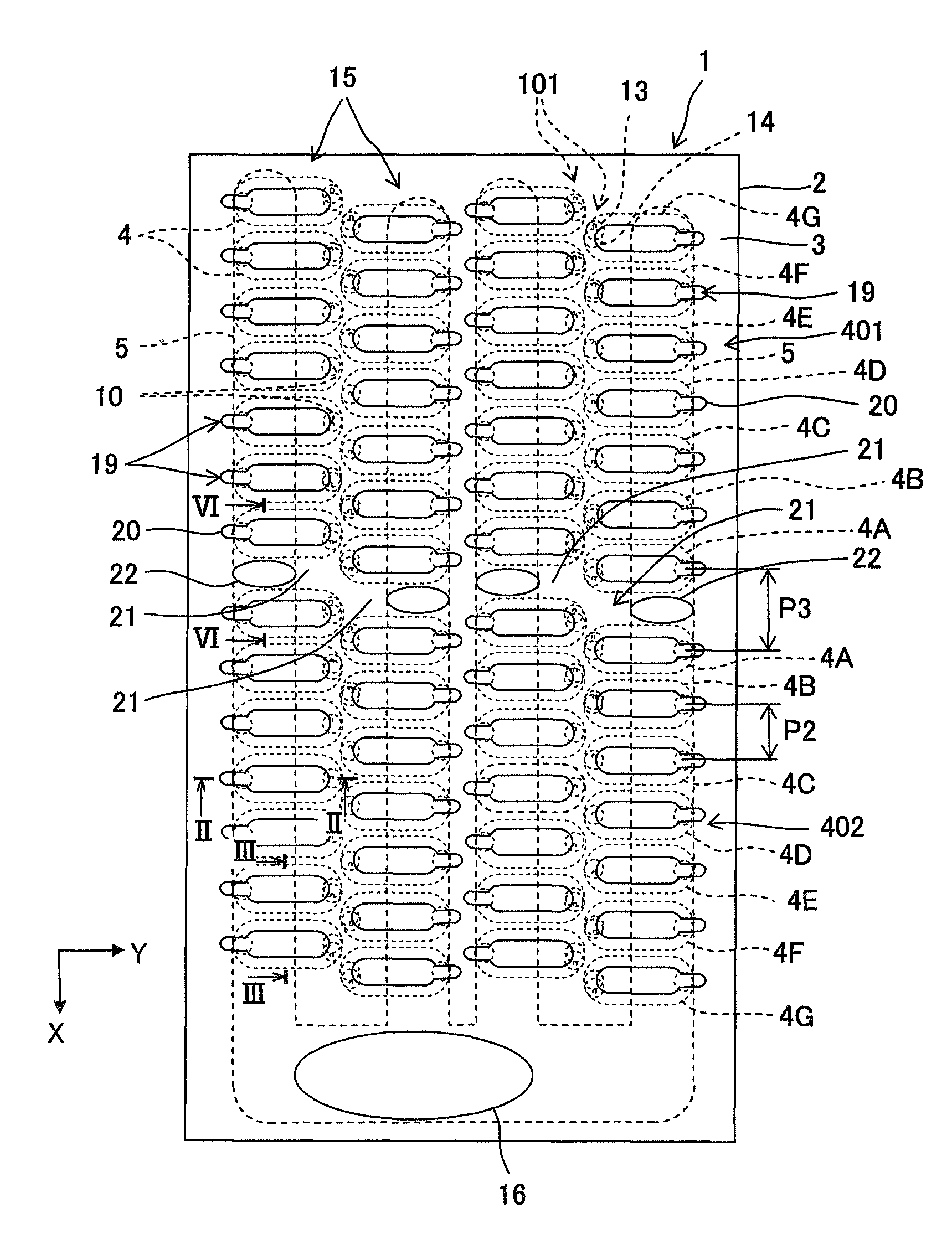
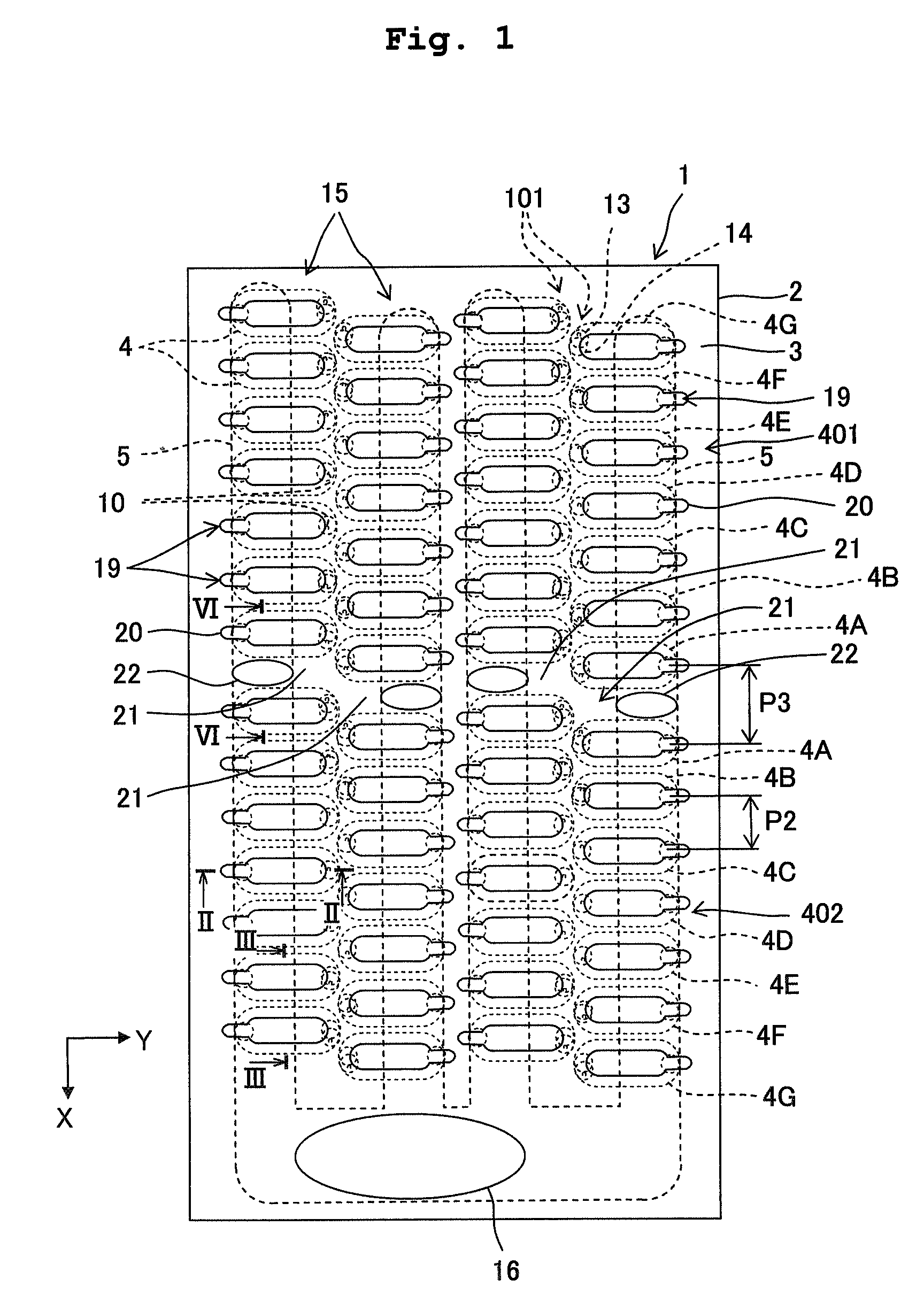
[0057]Exemplary embodiments of the present invention will be described below with reference to the accompanying diagrams. FIG. 1 is a plan view showing a head 1 (a liquid droplet jetting head, an ink-jet head) according to a first embodiment of the present invention as viewed from a top. The head 1 includes mainly a channel unit 2 in which a plurality of substantially rectangular shaped plates are stacked, and a piezoelectric actuator 3 (pressure applying mechanism) which is joined to the channel unit 2. Moreover, a flexible circuit board not shown in the diagram is joined to an upper surface of the piezoelectric actuator 3. A drive circuit which outputs a driving signal for the piezoelectric actuator 3 is arranged on the flexible circuit board. In the following description, as shown by arrows in FIG. 1, a longitudinal direction of the head 1 is defined as X direction and a direction of a short side (a direction orthogonal to the longitudinal direction) is defined as Y direction.

[00...

second embodiment

[0082]FIG. 7 is a plan view when a head 25 according to a second embodiment of the present invention is viewed from a top. FIG. 8 is a cross-sectional view taken along an VIII-VIII line in FIG. 7. Communication passages as auxiliary supply passages are provided to the head 25 of the second embodiment, instead of the sub ink supply passages 22 of the head 1 of the first embodiment. In the following description, each of the plurality of common liquid chambers 5 in FIG. 7 are called as a first common liquid chamber 5A, a second common liquid chamber 5B, a third common liquid chamber 5C, and a fourth common liquid chamber 5D in order from a left side. One of first communicating passages 26 which passes through a space 21 corresponding to the first common liquid chamber 5A and a space 21 corresponding to the second common liquid chamber 5B, and which makes communicate between the second common liquid chambers 5A and 5B is formed. Moreover, similarly, the other of the first communicating ...

third embodiment

[0087]FIG. 9 is a plan view when a head 30 according to a third embodiment of the present invention is viewed from a top. FIG. 10 is a plan view when a flexible wire 31 to be connected to the head 30 is viewed from a top. The head 30 of the third embodiment differs from the heads of the first embodiment and the second embodiment at a point that, the sub ink supply passage 22, and the first communicating passage 26 and the second communicating passage 27 are formed. The first communicating passage 26 and the second communicating passage 27 are formed similarly as in the second embodiment. The sub ink supply passage 22 is formed only for the first common liquid chamber 5A and the second common liquid chamber 5B. In the head 30 of the third embodiment, the ink circulates between the common liquid chambers 5 through the first communicating passage 26 and the second communicating passage 27. Further, since the ink is supplied from outside of the head 30 via the sub ink supply passage 22,...


PUM


Abstract

A plurality of pressure chambers are divided into a first pressure chamber group and a second pressure chamber group, and are arranged such that an interval of the first pressure chamber group and the second pressure chamber group is larger than an interval between nozzles, and sub ink supply passage which supplies the ink to the common liquid chambers through the space is formed. Accordingly, a liquid droplet jetting head which is capable of delivering the ink to all the nozzles without increasing a size is provided.

Description

CROSS REFERENCE TO RELATED APPLICATION[0001]The present application claims priority from Japanese Patent Application No. 2007-341562, filed on Dec. 29, 2007, the disclosures of which are incorporated herein by reference in its entirety.BACKGROUND OF THE INVENTION[0002]1. Field of the Invention[0003]The present invention relates to a liquid droplet jetting head which is used in a liquid droplet jetting apparatus.[0004]2. Description of the Related Art[0005]As a liquid droplet jetting head, an ink-jet head which transports an ink supplied from an ink tank, and jets ink droplets from nozzles toward a recording paper has already been known. Types for jetting ink is classified according to a difference of a method of generation of a jetting energy. For example, there are types such as a thermal-jet type in which ink droplets are jetted by generating an air bubble by thermal (heat) energy.[0006]The liquid droplet jetting head described above, includes for example, a channel unit in which ...

Claims


Application Information

Patent Timeline
Patent Type & Authority Patents(United States)
IPC IPC(8): B41J2/045
CPCB41J2/14233B41J2002/14403B41J2002/14419B41J2002/14459B41J2002/14491
Inventor SUGAHARA, HIROTO
Owner BROTHER KOGYO KK
Why Eureka
Try Eureka