Wrench

a technology of wrenches and screws, applied in the field of wrenches, can solve the problems of cam abrasion, difficult operation, cam abrasion, etc., and achieve the effect of simple structure and excellent use

Active Publication Date: 2013-12-05
HSU CHANG HSUEH O
View PDF19 Cites 2 Cited by
  • Summary
  • Abstract
  • Description
  • Claims
  • Application Information

AI Technical Summary

Benefits of technology

[0008]The main object of the present invention is to provide a wrench which is simple in structure and has excellent effects of use.
[0014]The handle has a toggle member disposed at one end thereof. When the handle is at a driving position, the toggle member is located in the driving space and engages against the first end of the first lower enlarged portion, and the changeable opening has the smallest width. When the handle is at a releasing position, the toggle member is located away from the first end of the first lower enlarged portion and moves into the evading space from the driving space smoothly, and the movable jaw is capable of moving away from or toward the fixed jaw.
[0015]Whereby, the structure of the wrench of the present invention is simple, the manufacturing costs is decreased, and the force applied by the user can be sufficiently delivered to the movable jaw and the fixed jaw. Furthermore, the slidable member is provided with the evading space, so that the travel distance for which the movable jaw moves away from the fixed jaw is not limited.

Problems solved by technology

However, under a required huge torque, such an engagement between the cam portions can easily lead to the collapse of the cam portions and the abrasion of the cam portions after a prolonged use of the cam portions.
In other words, when the wrench which is provided without the use of the engagement of the cam portions is used, it is difficult to operate because only a small part of the force is delivered to the movable jaw and the fixed jaw.
The structure of the wrench is quite complex, thus increasing the manufacturing costs and assembly difficulty.

Method used


Image

  • Wrench
  • Wrench
  • Wrench

Examples


Embodiment Construction

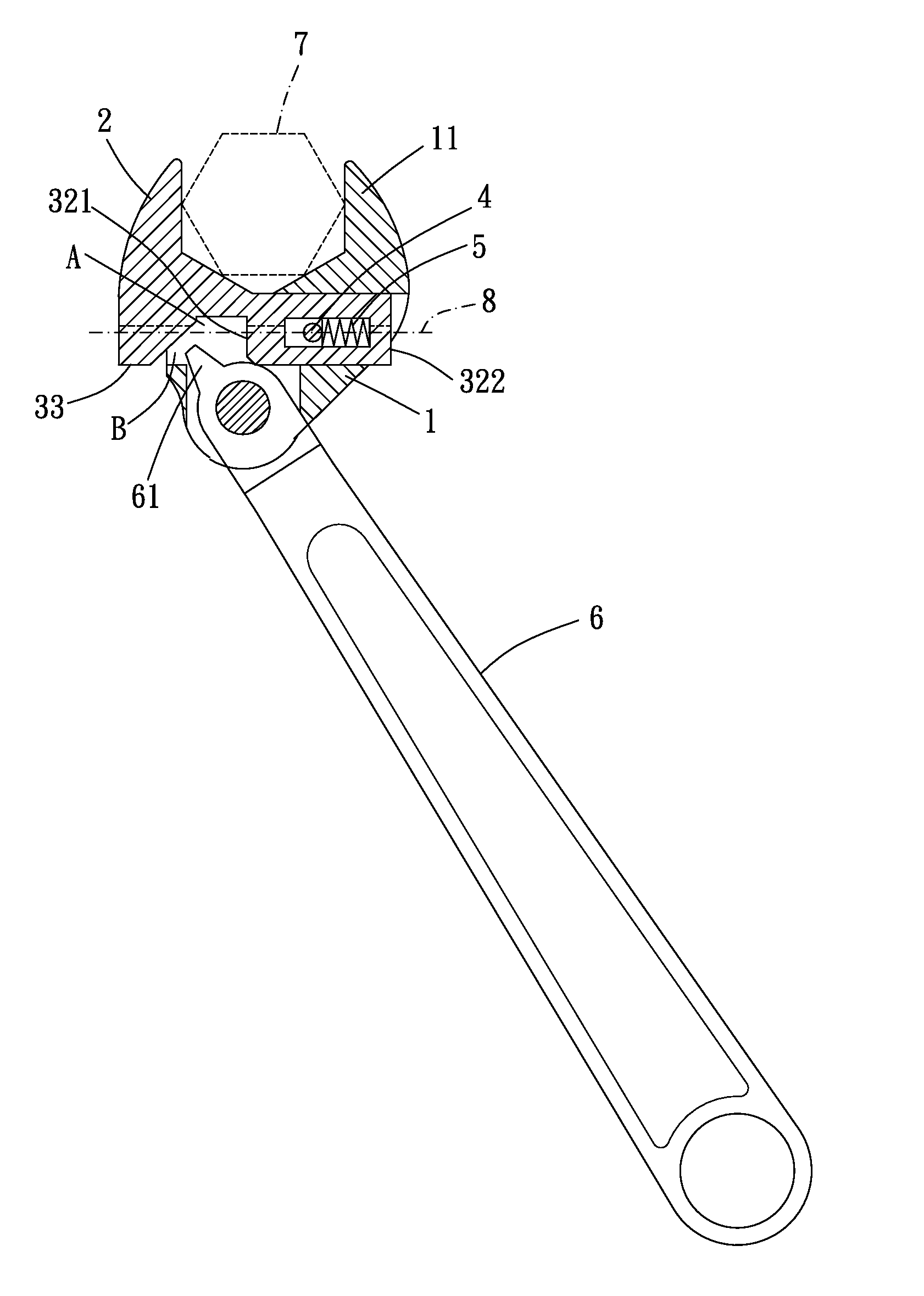
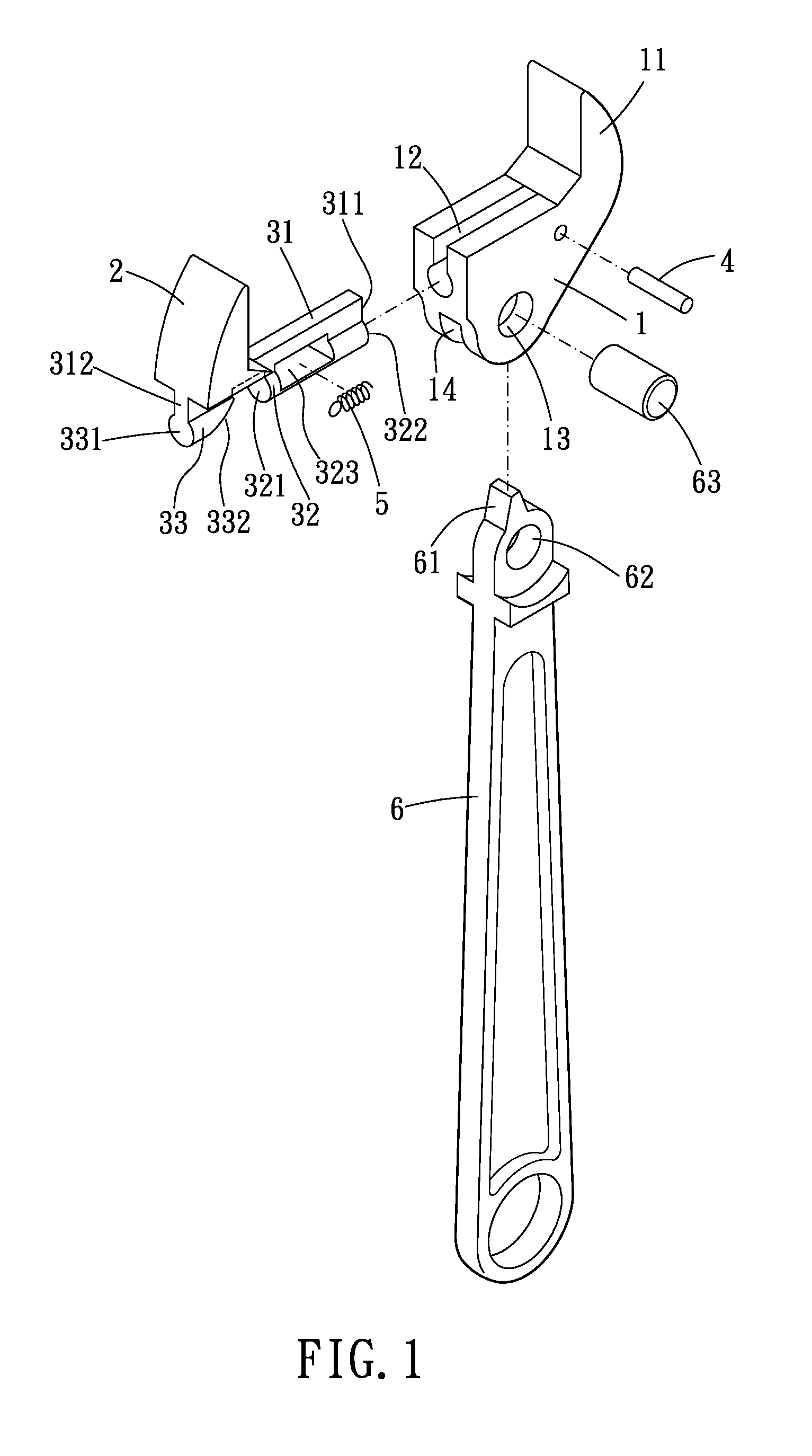
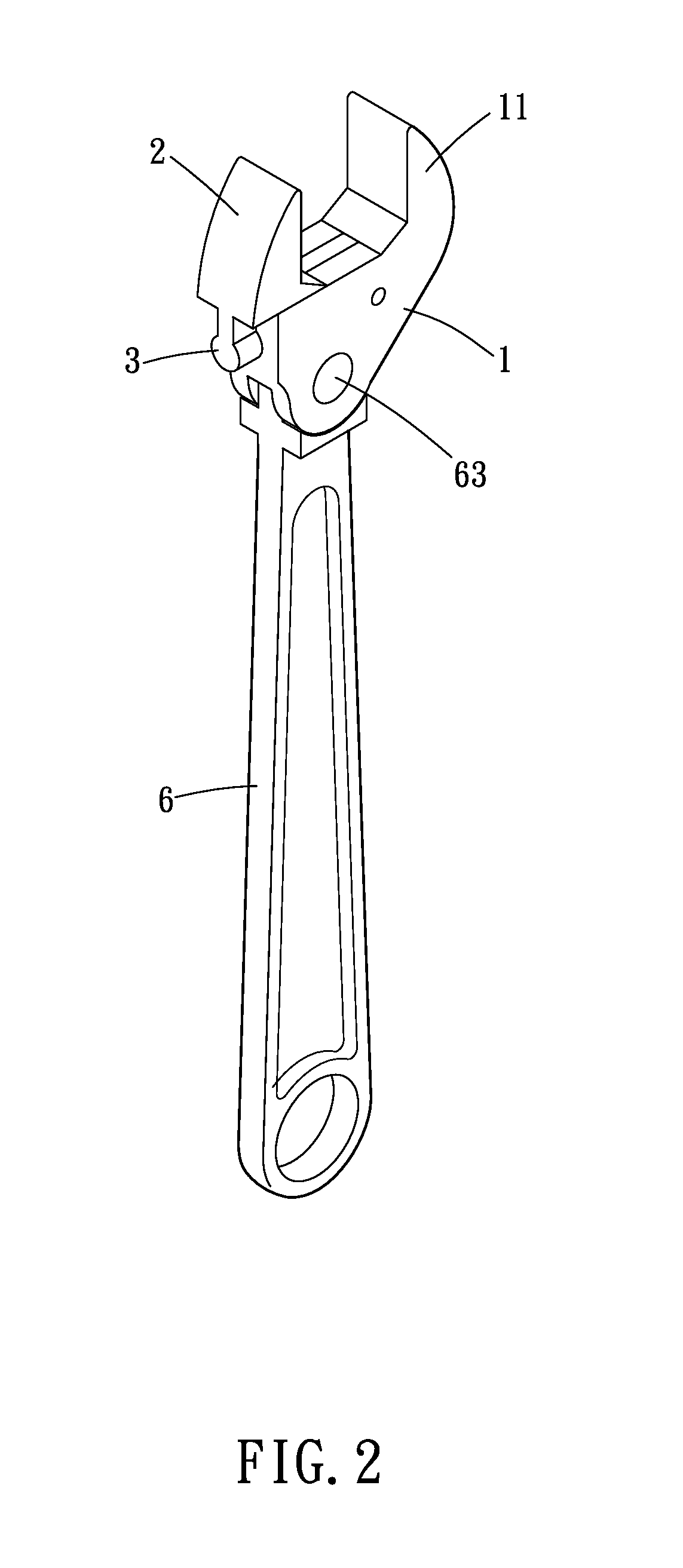
[0021]As shown in FIGS. 1 to 3, a wrench of the present invention includes a main body 1, a movable jaw 2, a slidable member 3, a blocking member 4, a spring member 5 and a handle 6.

[0022]The main body 1 has a fixed jaw 11. The main body 1 may further include a sliding slot 12, a through hole 13 and a through recess 14 for the assembly of other parts. The sliding slot 12, the through hole 13 and the through recess 14 communicate with each other, and the through hole 13 is located between the sliding slot 12 and the through recess 14. In addition, an axis of the through hole 13 is perpendicular to the direction in which the sliding slot 12 extends.

[0023]The slidable member 3 is integrally formed at the bottom portion of the movable jaw 2 and slidably mounted to the main body 1, more specifically, slidably mounted in the sliding slot 12 of the main body 1. The movable jaw 2 defines a changeable opening with the fixed jaw 11, and the width of the changeable opening can change when the ...


PUM


Abstract

The present invention provides a wrench which includes a movable jaw, a fixed jaw and a slidable member formed at the bottom portion of the movable jaw and slidably mounted to the main body. In the present invention, a toggle member can be driven to rotate through rotating a handle of the wrench, and the toggle member can smoothly move to and fro between a driving space and an evading space of the slidable member. Whereby, the present invention is simple in structure, has characteristics of smoothly engagedly-cooperative movements between parts of the wrench, so that it can make full use of the force applied by the user and has excellent effects of use.

Description

BACKGROUND OF THE INVENTION[0001]1. Field of the Invention[0002]The present invention relates to a wrench.[0003]2. Description of the Prior Art[0004]A conventional wrench is subjected to be used through the cooperative engagement of a cam portion disposed at the bottom of a movable jaw and another cam portion disposed at the top of a handle. However, under a required huge torque, such an engagement between the cam portions can easily lead to the collapse of the cam portions and the abrasion of the cam portions after a prolonged use of the cam portions.[0005]In this regard, a wrench disclosed in patent U.S. Pat. No. 1,434,754 is provided to improve the above problem, in which a spring is disposed in a slot, and rivets are secured to plates and located in the slot. However, since the cooperating projections are located below the slot, and so is the cam shaped projection, the force applied to the movable jaw by the cam shaped projection concentrates mostly at the cooperating projection...

Claims


Application Information

Patent Timeline
Patent Type & Authority Applications(United States)
IPC IPC(8): B25B13/46
CPCB25B13/46B25B13/18
Inventor HSU, CHANG HSUEH-O
Owner HSU CHANG HSUEH O
Why Eureka
Try Eureka