
Fletching for arrow

a technology of arrows and arrows, applied in the field of arrows, can solve the problems of difficult to impart the pitch, the arrow does not fly straight towards the target, so as to ensure the stability of the arrow in flight and ensure the linear travel of the arrow, the effect of easy mounting to the sha

Active Publication Date: 2011-10-18
SONG JIN HEE
View PDF5 Cites 18 Cited by
  • Summary
  • Abstract
  • Description
  • Claims
  • Application Information

AI Technical Summary

Benefits of technology

"The present invention provides a fletching for an arrow that maintains a predetermined shape, is lightweight, and controls the flow of air acting on the fletching to a proper level, thus ensuring in-flight stability and linear travel of the arrow. The fletching includes a wing part and an adhesive part. The wing part has a frame with a thin film, and a plurality of vertical ribs and horizontal ribs connecting the upper and lower portions of the frame to each other. The adhesive part is attached to the shaft. The wing part is curved at a predetermined angle by tension of the vertical ribs which connect the upper and lower portions of the frame to each other. The thin film is thinner than the frame, the vertical ribs, and the horizontal ribs, and the vertical ribs are thicker than the horizontal ribs."

Problems solved by technology

That is, the arrow does not fly straight towards a target but flies unsteadily as if it were a swimming fish.
However, the conventional fletching is problematic in that a worker or user must manually impart a pitch to the fletching 10, so that it takes a long time and is very difficult to impart the pitch.

Method used


Image

  • Fletching for arrow
  • Fletching for arrow
  • Fletching for arrow

Examples


first embodiment

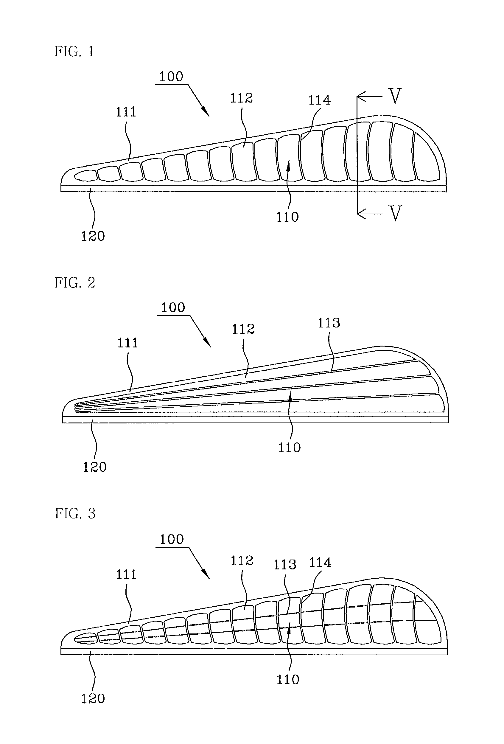
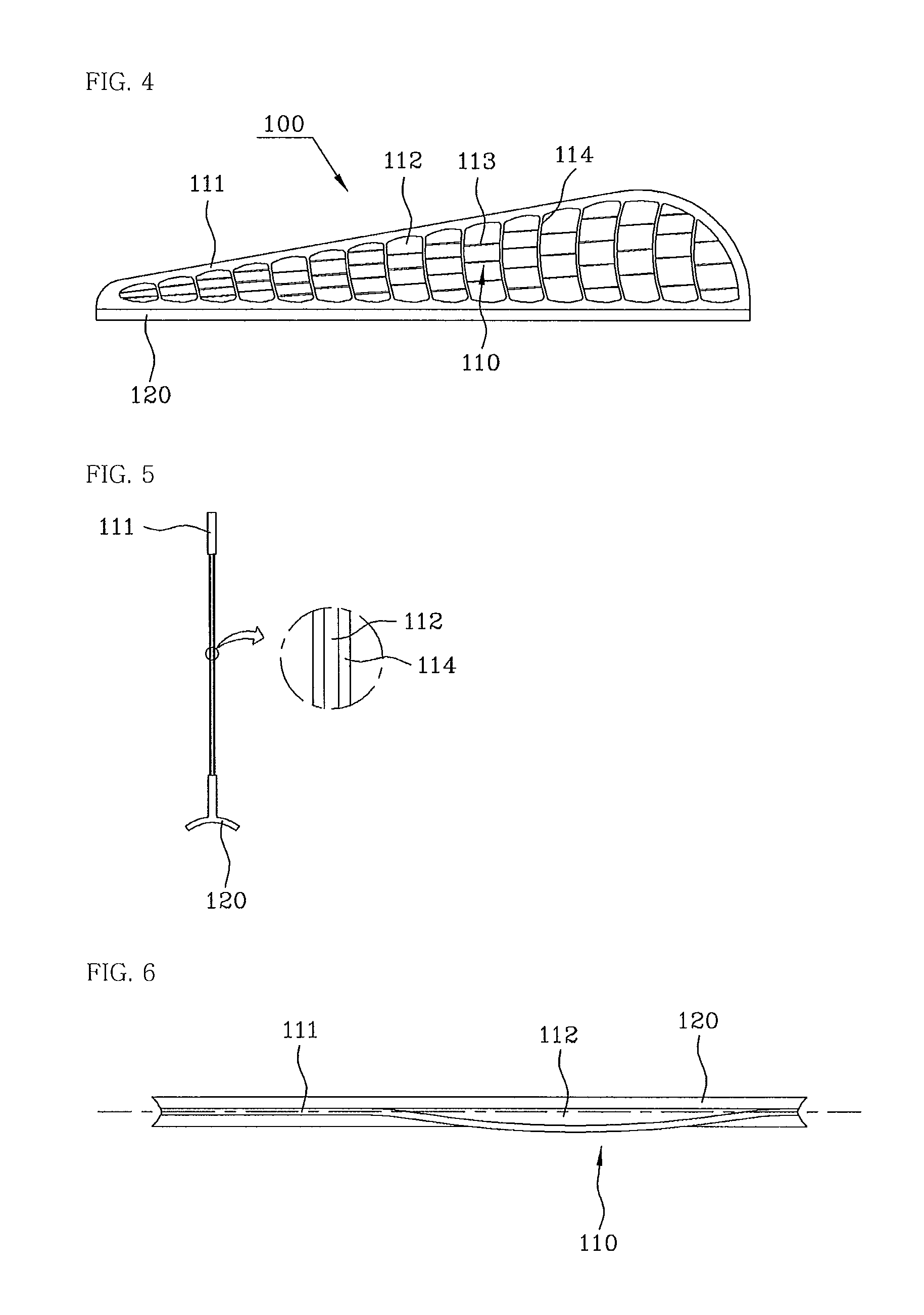
[0027]FIG. 1 is a side view illustrating fletching for an arrow according to the present invention, and FIG. 5 is a vertical sectional view taken along line V-V of FIG. 1. Fletching 100 for an arrow according to the present invention includes a wing part 110 which guides air resistance and imparts rotary force to a shaft, and an adhesive part 120 which is used to attach the wing part 110 to the shaft.

[0028]Unlike a conventional wing part which is made of a simple plate material, the wing part 110 includes a frame 111 which is formed such that the inside portion of its outer edge is open, thus defining an overall structure of the wing part 110, a plurality of vertical ribs 114 which connect the upper and lower portions of the frame 111 to each other and are arranged from the front of the fletching to the rear thereof in such a way as to be spaced apart from each other, and thin films 112.

[0029]The frame 111 is formed to have a predetermined thickness using a material such as resin, a...

second embodiment

[0031]FIG. 2 is a side view illustrating fletching for an arrow according to the present invention. Unlike the above embodiment, a wing part 110 includes a frame 111 which defines an overall structure of the wing part 110, a plurality of horizontal ribs 113 which connect the left and right portions of the frame 111 to each other and are arranged from the upper portion of the fletching to the lower portion thereof in such a way as to be spaced apart from each other, and thin films 112. Similarly to the vertical ribs 114, the horizontal ribs 113 may be made of the same material as the frame 111 or made of a material different from that of the frame 111.

third embodiment

[0032]FIG. 3 is a side view illustrating fletching for an arrow according to the present invention. According to this embodiment, in addition to the vertical ribs 114, the fletching includes a plurality of horizontal ribs 113 which connect the frame 111 to the vertical ribs 114 or connect vertical ribs 114 to each other. That is, the fletching additionally includes the horizontal ribs 113 which connect vertical ribs 114, selected from the plurality of vertical ribs 114 which are arranged from the front portion of the fletching 100 to the rear portion thereof, to each other. As such, in the case of forming the horizontal ribs 113 which connect the vertical ribs 114 to each other or connect the vertical ribs 114 to the frame 111, the shape of the wing part 110 can be more effectively maintained.

[0033]FIG. 4 is a side view illustrating fletching for an arrow according to a fourth embodiment of the present invention. According to this embodiment, horizontal ribs 113 are not arranged in ...


PUM


Abstract

Disclosed herein is fletching for an arrow, which is light and displays sufficient air resistance, thus ensuring the linear travel and stability of the flight of the arrow, being easy to attach to a shaft, and reliably maintaining the shape of the fletching. The fletching includes a wing part and an adhesive part. The wing part includes a frame formed such that an inside portion of an outer edge thereof is open and defining an overall structure, a plurality of vertical ribs connecting upper and lower portions of the frame to each other and arranged to be spaced apart from each other in a longitudinal direction of the frame, and a thin film provided in an empty space defined by the frame and each of the vertical ribs. The adhesive part is provided on the lower end of the wing part and attached to a shaft.

Description

BACKGROUND OF THE INVENTION[0001]1. Field of the Invention[0002]The present invention relates generally to fletching for an arrow and, more particularly, to fletching for an arrow which is lighter than conventional fletching, ensures in-flight stability and linear travel of the arrow, and imparts a pitch to a wing part in advance to allow the fletching to be easily mounted to a shaft.[0003]2. Description of the Related Art[0004]An arrow is a projectile which straddles the string of a bow or crossbow to be shot therefrom, and includes a shaft, a pile, fletching and a nock. The pile is provided on the front end of the shaft, and the nock is provided on the rear end of the shaft to straddle the string of the bow or crossbow. Generally, the arrow which has been shot from the string of the bow or crossbow flies to a target while describing a parabola. At this time, the arrow flies while rolling and pitching with respect to the center of gravity of the arrow. That is, the arrow does not f...

Claims


Application Information

Patent Timeline
Patent Type & Authority Patents(United States)
IPC IPC(8): F42B6/06
CPCF42B6/06
Inventor SONG, IN-GYU
Owner SONG JIN HEE
Learn More