Power Paddle

a power tool and paddle technology, applied in the field of boat paddles, can solve the problems of user rapidity and ground cover, and achieve the effects of smooth and easy movement of the boat, less turbulence, and increased thrus

Inactive Publication Date: 2007-09-27
PRODUCT DEVELOPMENT TECHNOLOGIES
View PDF5 Cites 6 Cited by
  • Summary
  • Abstract
  • Description
  • Claims
  • Application Information

AI Technical Summary

Benefits of technology

[0013]When using this paddle as part of a power tool attachment, the paddle together with the power tool will be mounted onto the boat in a manner that provides for stable boat travel. The power tool will be set in the on position and will force water though the paddle turning a propeller within the paddle. This will smoothly and easily move a boat across the water. During this time, a user can rest or is free to partake in any other activity that may need his attention on the boat.
[0014]This invention utilizes shrouded propellers. These shrouded propellers are advantageous because this invention will cause the user to experience less turbulence. The clearance between the shroud and the propeller is to be high so that thrust can be increased. When the clearance between the shroud and propeller is tight, the propeller will likely gain force but lose thrust. The shroud also provides a user with more safety as typical propellers are not covered in any way. Uncovered propellers may be dangerous and cause injury to a user in some instances. The shroud also helps to keep weeds or grass in the water out of the propeller.
[0015]Also reducing turbulence in the water is the fact that the supports to the propeller are far enough away to reduce typical turbulence.

Problems solved by technology

A paddle that is extremely heavy will tire a user quickly and result in less ground to be covered.

Method used


Image

  • Power Paddle
  • Power Paddle
  • Power Paddle

Examples


Embodiment Construction

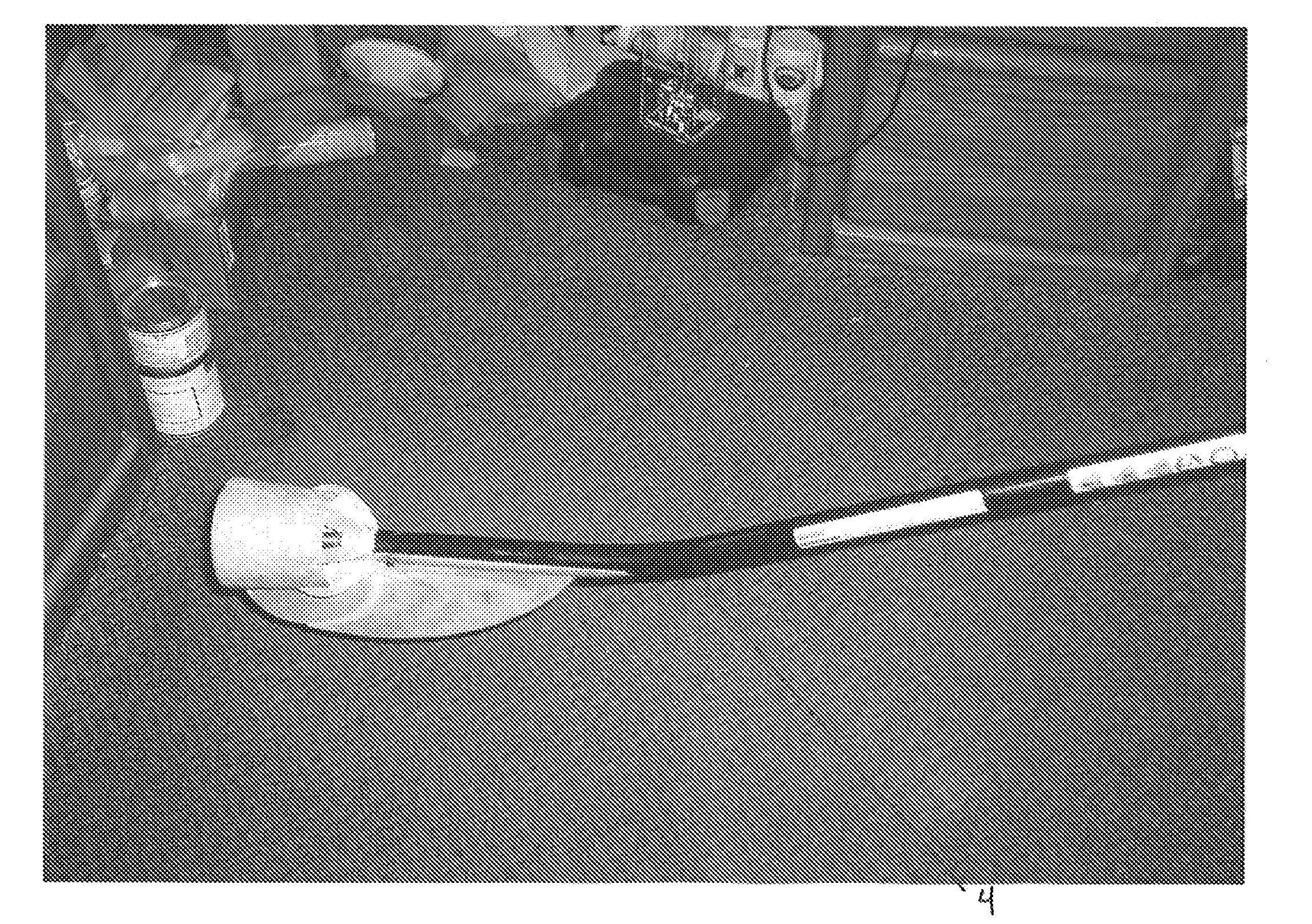
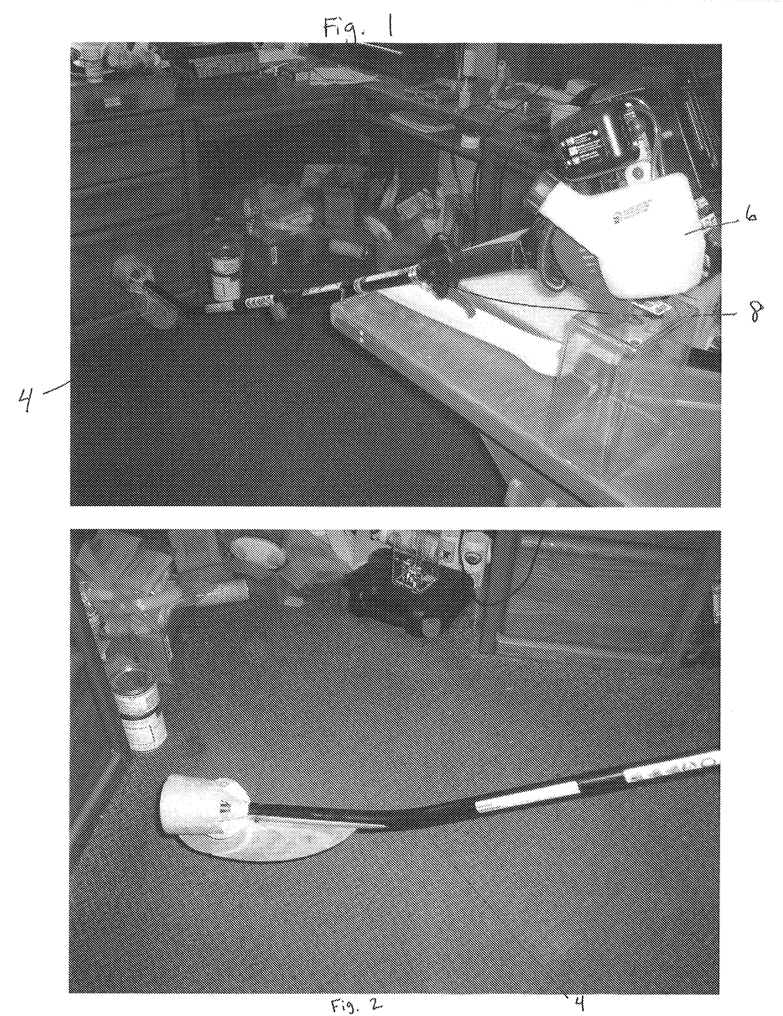
[0023]In the figures, the paddle 4 is attached to the power tool 6 by a means of attachment 8. The paddle 4 is a lightweight paddle designed to perform dual functions. One function is to perform as a standard rowing paddle. The paddle 4 is to be manually used by a boater and is to be paddled in the customary manner. A second function is to perform as powered paddle by means of the power tool 6.

[0024]When used as a powered paddle, the paddle 4, is attached to the power tool 6 by means of attachment 8. This means of attachment is seen in FIG. 1 as a latch. While a latch is depicted, other attachment mechanisms can be anticipated. This means of attachment 8 provides for easy attachment or detachment of the paddle 4 from the power tool 6.

[0025]The power tool 6 seen in the Figures is a grass and weed trimmer. This particular power tool 6 is a preferred power tool 6 as it is capable of generating enough force to safely move a water vehicle, however other power tools may be used just as ea...


PUM


Abstract

This invention relates to a paddle for a water vehicle that is powered by a power tool. The paddle is suitable for use alone for manual movement of a water vehicle but can be attached to a power tool for mechanical movement across water.

Description

FIELD OF THE INVENTION[0001]This invention relates to a boat paddle. More specifically it relates to the field of a power tool powered paddle for use in conjunction with boating. This invention describes a paddle that performs as an attachment to a machine as well as a basic manual paddle.BACKGROUND OF THE INVENTION[0002]Boat paddles have been in existence for centuries. Since the beginning of travel by water, users have had to use one of many variations of a paddle to maneuver the water. Over time, boats have developed to the point where paddles and the art of paddling has become more and more of a recreational sport then a necessity. Paddling a boat, especially a canoe, is seen as a way for a user to exercise and enjoy the outdoors. Canoeing trips typically coincide with a camping experience so many times a user will carry equipment in the boat as a way to comfortably travel and vacation.[0003]Boaters who paddle for recreational purposes generally are always looking for the next d...

Claims


Application Information

Patent Timeline
Patent Type & Authority Applications(United States)
IPC IPC(8): B63H16/04
CPCB63H5/14B63H20/00B63H16/04B63H5/18
Inventor KUDRNA, OTAKAR
Owner PRODUCT DEVELOPMENT TECHNOLOGIES
Why Eureka
Try Eureka