Robot cleaner and control method thereof

a robot cleaner and control method technology, applied in the field of robot cleaners, can solve the problems of robot cleaners that cannot obtain a sufficient frictional force when their wheels are rolled, the wheel mechanism such as the gear may be damaged by an external shock, and the robot cleaner may be stuck and immobil

Active Publication Date: 2018-03-06
SAMSUNG ELECTRONICS CO LTD
View PDF12 Cites 5 Cited by
  • Summary
  • Abstract
  • Description
  • Claims
  • Application Information

AI Technical Summary

Benefits of technology

[0010]Therefore, it is an aspect of the present disclosure to provide a robot cleaner having an improved wheel structure to escape from being stuck in various travel conditions, and a control method thereof.
[0012]Still another aspect of the present disclosure provides a robot cleaner that may stably travel without shaking by controlling an electric current flowing through the motor after the robot cleaner escapes from being stuck and before the driving wheel returns to a normal mode.
[0025]The controller may increase the output of the second driving motor to rotate the wheel frame between a third position and a second position when the robot cleaner is lifted and thus stuck.

Problems solved by technology

There are obstacles such as an edge protrusion (a door sill), an object having an inclined surface, and furniture in the cleaning region in which the robot cleaner travels.
That is, the robot cleaner may be stuck and immobile.
However, since the related art robot cleaner depends on the force of the spring, the robot cleaner cannot obtain a sufficient frictional force when its wheel is lifted.
In addition, since the wheel is lifted high irrespective of the height of the obstacle, a wheel mechanism such as a gear may be damaged by an external shock (e.g., which is caused by a pet or an object drop) or a shock caused by autonomous vibration when the robot cleaner crosses over the obstacle.
Furthermore, since the robot cleaner crosses over the obstacle while its wheel is inappropriately lifted high, the robot cleaner may be rattled and also cannot travel naturally.
The controller may determine that the robot cleaner is lifted and thus stuck when the electric current measured by the current sensor decreases to below a certain electric current.

Method used


Image

  • Robot cleaner and control method thereof
  • Robot cleaner and control method thereof
  • Robot cleaner and control method thereof

Examples


Embodiment Construction

[0064]Reference will now be made in detail to the embodiments of the present disclosure, examples of which are illustrated in the accompanying drawings, wherein like reference numerals refer to like elements throughout.

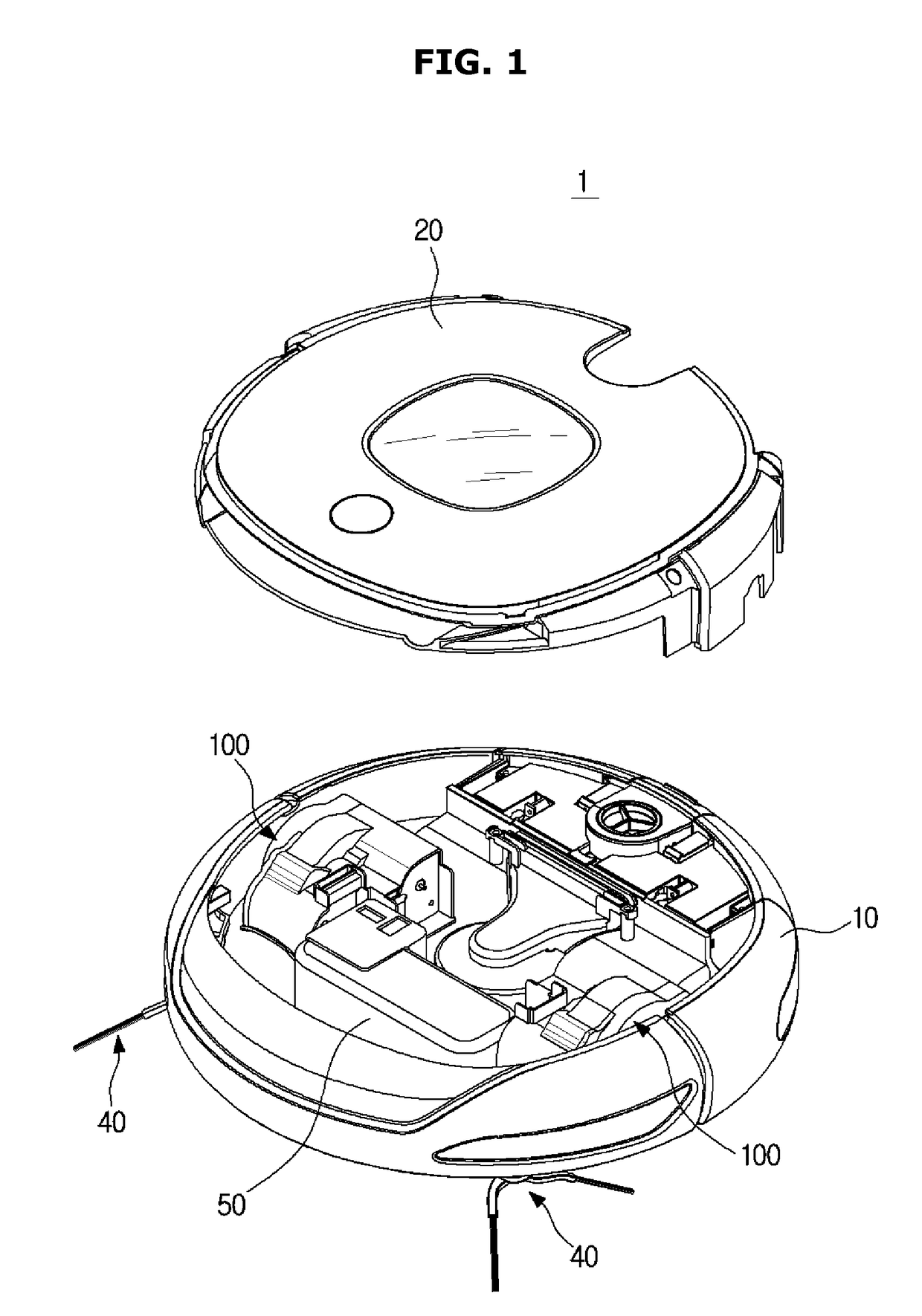
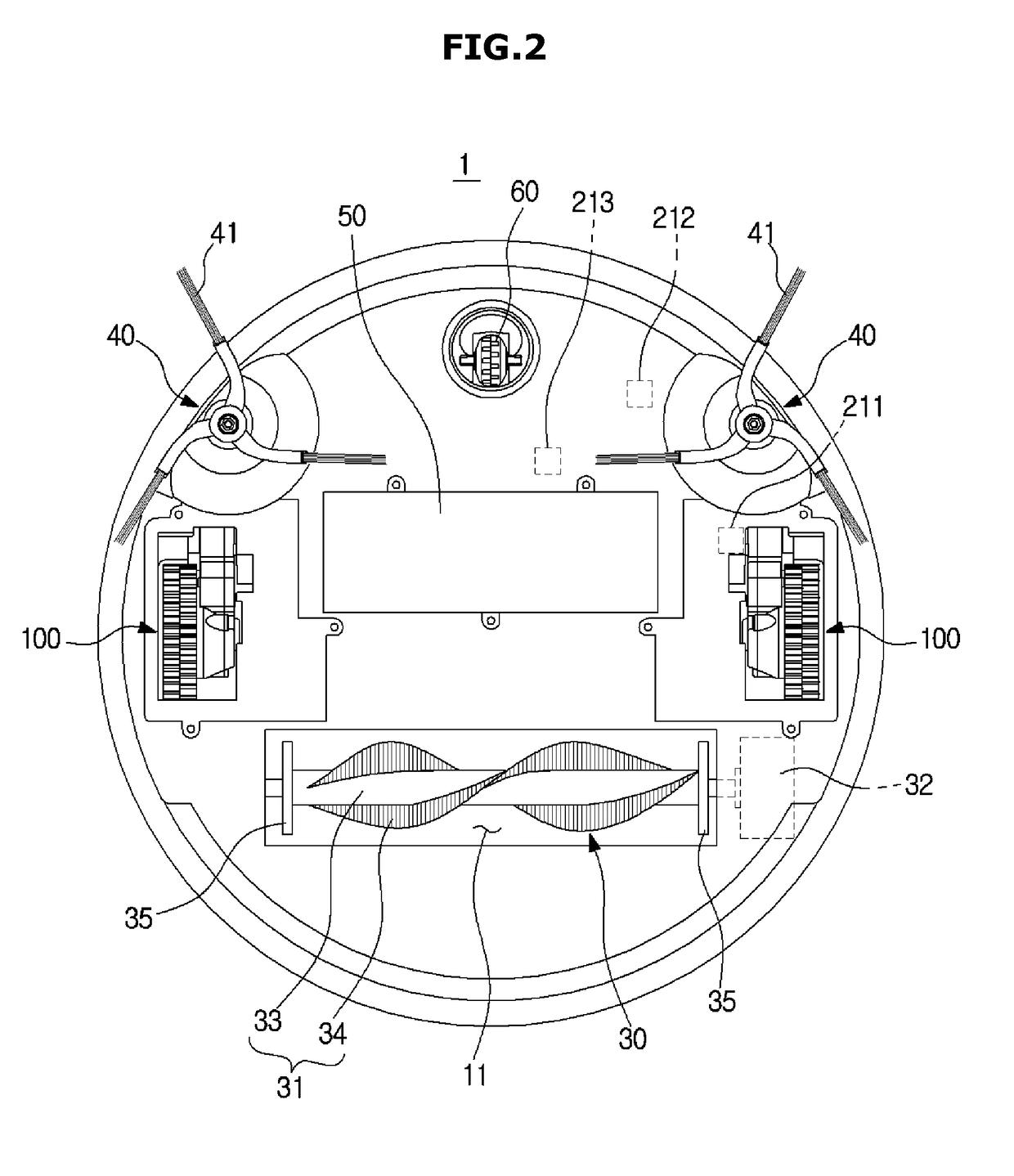
[0065]FIG. 1 is a view showing a configuration of a robot cleaner according to an embodiment of the present disclosure, and FIG. 2 is a bottom view of a robot cleaner according to an embodiment of the present disclosure.

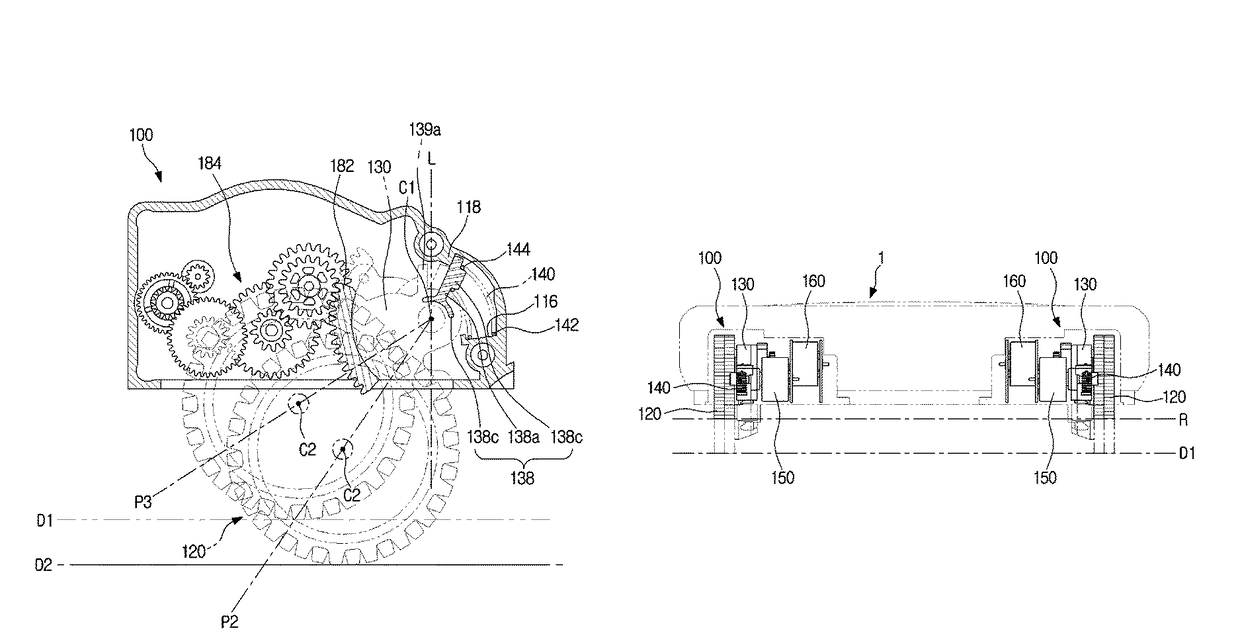
[0066]Referring to FIGS. 1 and 2, a robot cleaner 1 according to an embodiment of the present disclosure includes a main body 10 forming an external appearance of the robot cleaner 1, a cover 20 configured to cover a top of the main body 10, brushers 30 and 40 configured to sweep or scatter dust in a cleaning space, a power source 50 configured to supply driving power to drive the main body 10, and a driving unit 100 configured to drive the main body 10.

[0067]The main body 10 supports various kinds of components installed therein in addition to forming...


PUM


Abstract

Proposed are a robot cleaner having an improved wheel structure to escape from being stuck in various travel conditions, and a control method thereof. The robot cleaner may smoothly escape from a door sill or an obstacle to stably travel irrespective of a state of a floor by providing an optimal frictional force of the floor through the control of an electric current of a motor when the robot cleaner escapes from being stuck. Also, the robot cleaner may stably travel without shaking by controlling an electric current flowing through the motor after the robot cleaner escapes from being stuck and before the driving wheel returns to a normal mode. Furthermore, it is possible to prevent a wheel mechanism such as a gear from being damaged by an external shock (e.g., which is caused by a pet or an object drop) or a shock caused by autonomous vibration when the robot cleaner crosses over an obstacle.

Description

CROSS-REFERENCE TO RELATED APPLICATION[0001]This application claims the benefit of Korean Patent Application No. 2015-0030706, filed on Mar. 5, 2015 in the Korean Intellectual Property Office, the disclosure of which is incorporated herein by reference.BACKGROUND[0002]1. Field[0003]Embodiments of the present disclosure relate to a robot cleaner with an improved travel performance and a control method thereof.[0004]2. Description of the Related Art[0005]In general, a robot cleaner is a device that automatically cleans a region desired to be cleaned without a user's manipulation by sucking up foreign substances such as dust from floors while autonomously travelling in the region.[0006]Such a robot cleaner has a pair of driving wheels installed in both sides of a lower part of its main body and includes one or more casters needed to support the main body in order to turn or move the main body forward or backward in a cleaning region. There are obstacles such as an edge protrusion (a do...

Claims


Application Information

Patent Timeline
Patent Type & Authority Patents(United States)
IPC IPC(8): B60L15/20A47L11/40B60G17/016B60G17/019A47L9/28G05D1/02
CPCB60L15/20A47L9/2831A47L11/40B60G17/019B60G17/016Y02T10/7258A47L2201/00G05D1/00G05D1/02Y02T10/72A47L9/2852B25J13/08
Inventor PARK, SUNG JINLEE, DONG HUNPARK, HEUM YONGLEE, DONG-HYUN
Owner SAMSUNG ELECTRONICS CO LTD
Why Eureka
Try Eureka