Mechanism for restricting lateral position of tape traveling in longitudinal direction

a technology of longitudinal direction and lateral position, which is applied in the direction of printing, instruments, transportation and packaging, etc., can solve the problems of inability to properly read and write information from/to the tape, inability to disclose means, and high final product cost, etc., and achieve the effect of stably traveling and low cost fabrication

Inactive Publication Date: 2001-09-13
NEC CORP
View PDF6 Cites 5 Cited by
  • Summary
  • Abstract
  • Description
  • Claims
  • Application Information

AI Technical Summary

Benefits of technology

0012] The present invention is made from the above-described point of view. An object of the present invention is to provide a tape traveling restricting device that allows a tape to be stably traveled and that is fabricated at low cost.

Problems solved by technology

As a result, since the tape is unstably traveled, information cannot be correctly read and written from / to the tape.
Thus, the final product becomes expensive.
The above-described documents do not disclose means for solving such disadvantages.

Method used


Image

  • Mechanism for restricting lateral position of tape traveling in longitudinal direction
  • Mechanism for restricting lateral position of tape traveling in longitudinal direction
  • Mechanism for restricting lateral position of tape traveling in longitudinal direction

Examples


Embodiment Construction

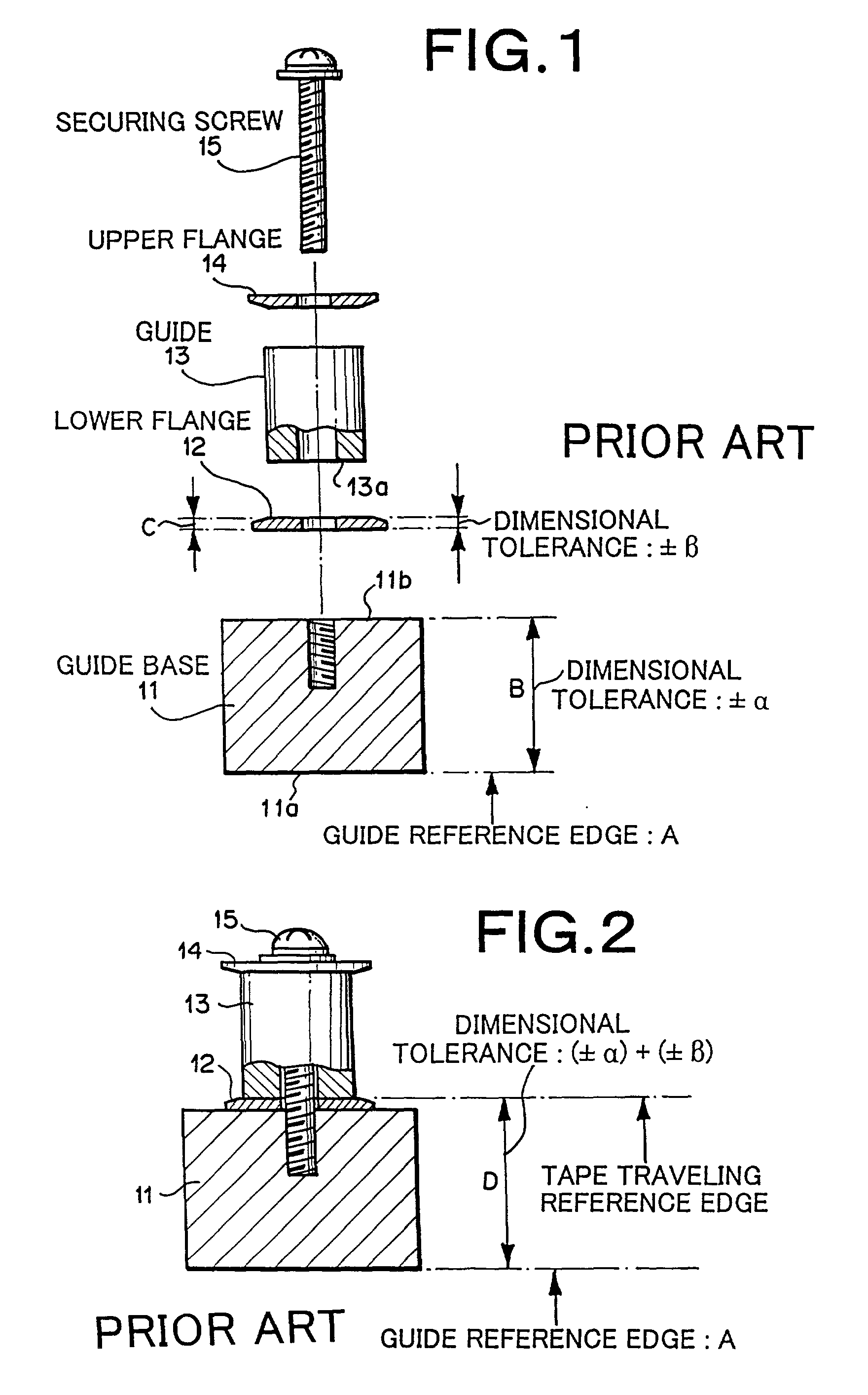
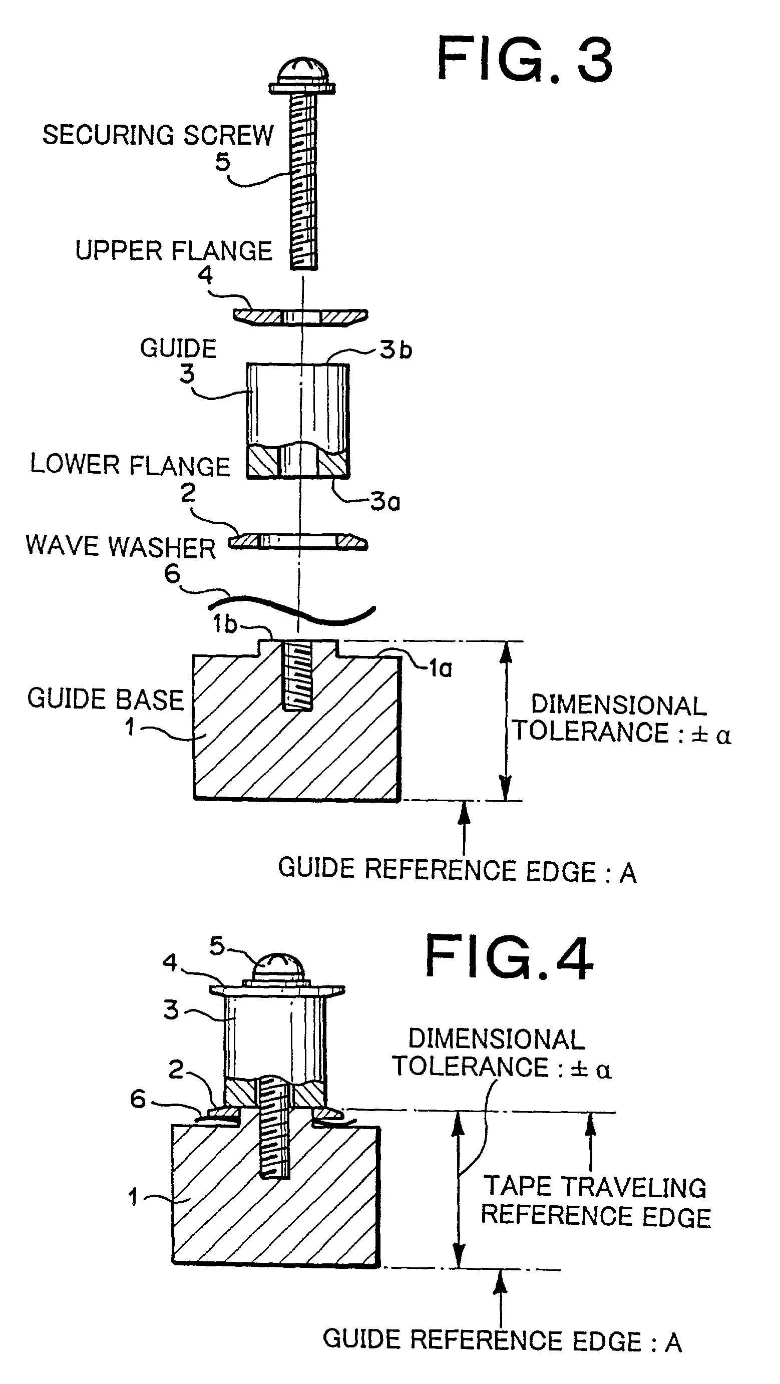
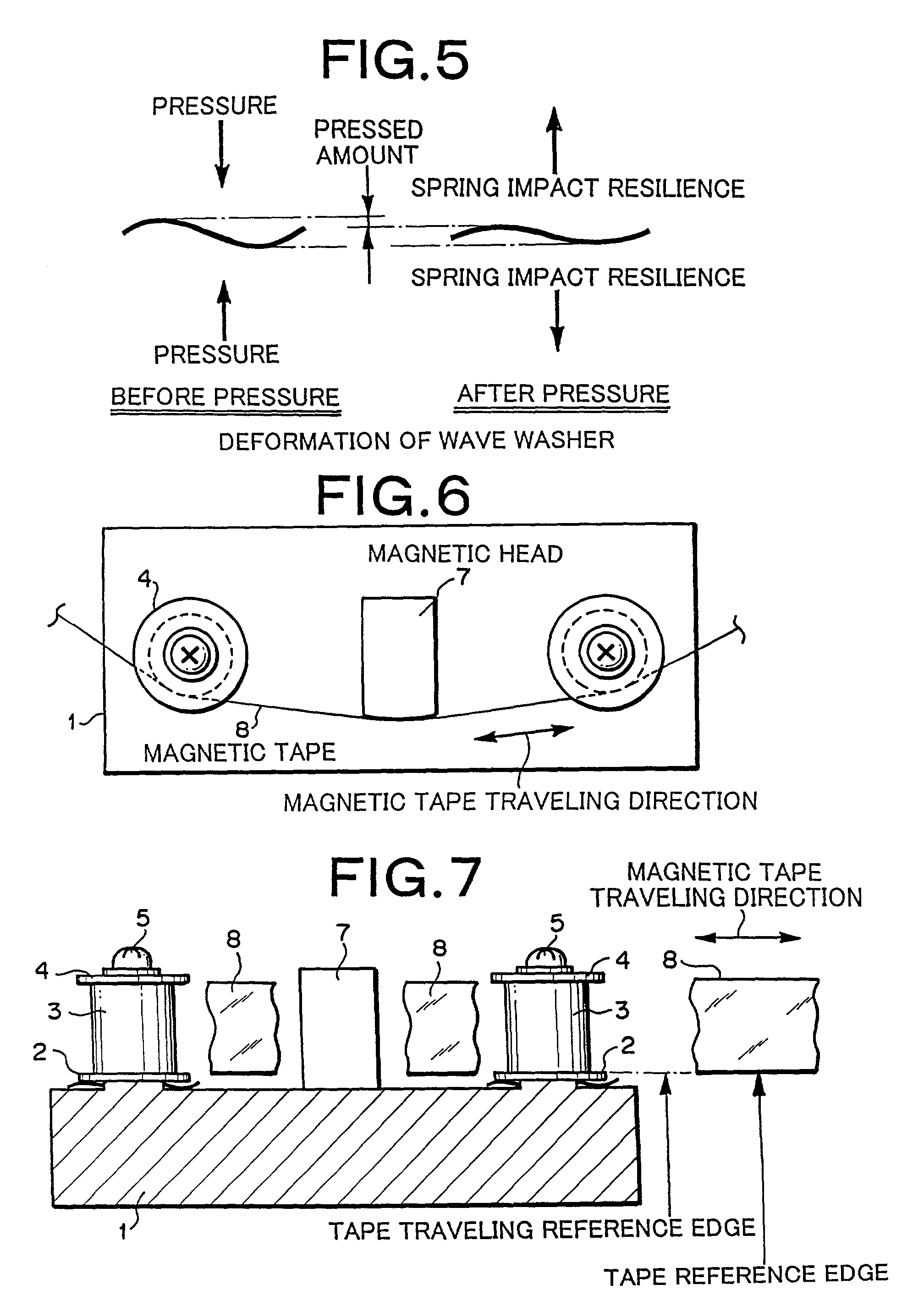
[0031] Next, with reference to the accompanying drawings, a preferred embodiment of the present invention will be described. FIG. 3 is a disassembled view showing the structure of a tape traveling restricting device according to the preferred embodiment of the present invention. FIG. 4 is an assembled view showing the structure of the tape traveling restricting device shown in FIG. 3. FIG. 5 is a schematic diagram showing a deformation of a wave washer (that will be described later). FIG. 6 is a plan view showing the overall structure of a guide base portion. FIG. 7 is a front view showing the overall structure of the guide base portion shown in FIG. 6.

[0032] First of all, the overall structure of the guide base portion will be described. Referring to FIGS. 6 and 7, two sets of lower flanges 2, guides 3, upper flanges 4, and securing screws 5 are symmetrically disposed as left and right assemblies at left and right positions on the upper edge of a guide base 1. A magnetic head 7 is ...


PUM

PropertyMeasurementUnit
structureaaaaaaaaaa
thicknessaaaaaaaaaa
inner diameteraaaaaaaaaa

Abstract

A mechanism for restricting a lateral position of a tape traveling in a longitudinal direction is disclosed, that comprises a base having a convex portion, a guide directly disposed on the convex portion, a lower flange having an opening through which the convex portion passes, the lateral position of said lower flange against said base being movable between the front edge of said base and the bottom edge of said guide, and a member for pressing said lower flange to the bottom edge of said guide.

Description

BACKGROUND OF THE INVENTION[0001] 1. Field of the Invention[0002] The present invention relates to a mechanism for restricting the lateral position of a tape traveling in the longitudinal direction and in particular, to that for use with a magnetic tape device.[0003] 2. Description of the Prior Art[0004] FIG. 1 is a disassembled view showing an example of the structure of a conventional tape traveling restricting device. FIG. 2 is an assembled view showing the structure of the tape traveling restricting device shown in FIG. 1. Referring to FIG. 1, the conventional tape traveling restricting device comprises a guide base 11, a lower flange 12, a guide 13, an upper flange 14, and a securing screw 15. The securing screw 15 has a thread portion. The thread portion is formed at a forward edge of the securing screw 15. The lower flange 12, the guide 13, and the upper flange 14 have respective openings through which the securing screw 15 smoothly passes. Likewise, the guide base 11 has a t...

Claims


Application Information

Patent Timeline
Patent Type & Authority Applications(United States)
IPC IPC(8): G11B15/60G11B15/62
CPCG11B15/605G11B15/62
Inventor OJIMA, KENICHI
Owner NEC CORP
Why Eureka
Try Eureka