Recording tape cartridge

a tape cartridge and tape technology, applied in the field of recording tape cartridges, can solve the problems of easy self-excited vibration, general problem of self-excited vibration, and difficulty in completely preventing, and achieve the effect of suppressing vibration

Inactive Publication Date: 2005-06-16
FUJIFILM CORP +1
View PDF8 Cites 6 Cited by
  • Summary
  • Abstract
  • Description
  • Claims
  • Application Information

AI Technical Summary

Benefits of technology

[0026] In view of the above, the present invention realizes a recording tape cartridge, which can suppress vibration generated by sliding contact between a member elastically supported on a case and a reel or a member rotating together with the reel.
[0031] In this case, a relational expression, μ×L≦0.4, which represents the relation between the length (hereinafter referred to as a load length of an elastic member) L of the elastic member along the axis line of the reel when the reel is rotated and the coefficient of dynamic friction μ between the pressed member and the reel or the like is a discriminant of stability. When the relation determined by the expression is not satisfied, amplitude of self-excited vibration of the pressed member may increase (oscillate) with a lapse of time. However, when the relation expressed by the expression is satisfied, self-excited vibration of the pressed member caused by sliding contact between the pressed member and the reel or the like during rotation of the reel is attenuated. More specifically, in this configuration which satisfies the discriminant for stability, vibration of the pressed member (periodical motion) is eliminated, or the amplitude of the vibration is considerably reduced.
[0032] In this manner, in the recording tape cartridge according to the present invention, vibration generated by sliding contact between the member elastically supported on the case and the reel or the member rotating together with the reel can be suppressed. For this reason, change in a biasing force of the elastic member with vibration of the pressed member can be suppressed, and the recording tape can be caused to stably travel. In addition, the load length L of the elastic member and the coefficient of dynamic friction μ are set to make it possible to prevent or suppress self-excited vibration of the pressed member. For this reason, the manufacturing cost of the recording tape cartridge can be reduced because the number of parts does not increase, in contrast with a configuration in which a vibration attenuating member or the like for reducing vibration of a pressed member is provided.
[0034] As described above, the recording tape cartridge according to the invention has the advantage of being able to suppress vibration generated by sliding contact between the member elastically supported on the case and the reel or a member rotating together with the reel.

Problems solved by technology

However, with such a configuration, it is difficult to completely prevent the abrasion which causes self-excited vibration to easily occur in the braking member 220 as described above.
Furthermore, the problem of the self-excited vibration may generally arise not only in a lock mechanism, which locks rotation of the reel in a nonuse state but also in a portion which is elastically supported and brought into sliding contact with a rotating portion as the reel rotates.

Method used


Image

  • Recording tape cartridge
  • Recording tape cartridge
  • Recording tape cartridge

Examples


Embodiment Construction

[0052] A recording tape cartridge 10 according to an embodiment of the present invention will be described below with reference to FIGS. 1A to 7B.

(Overall Configuration of Recording Tape Cartridge)

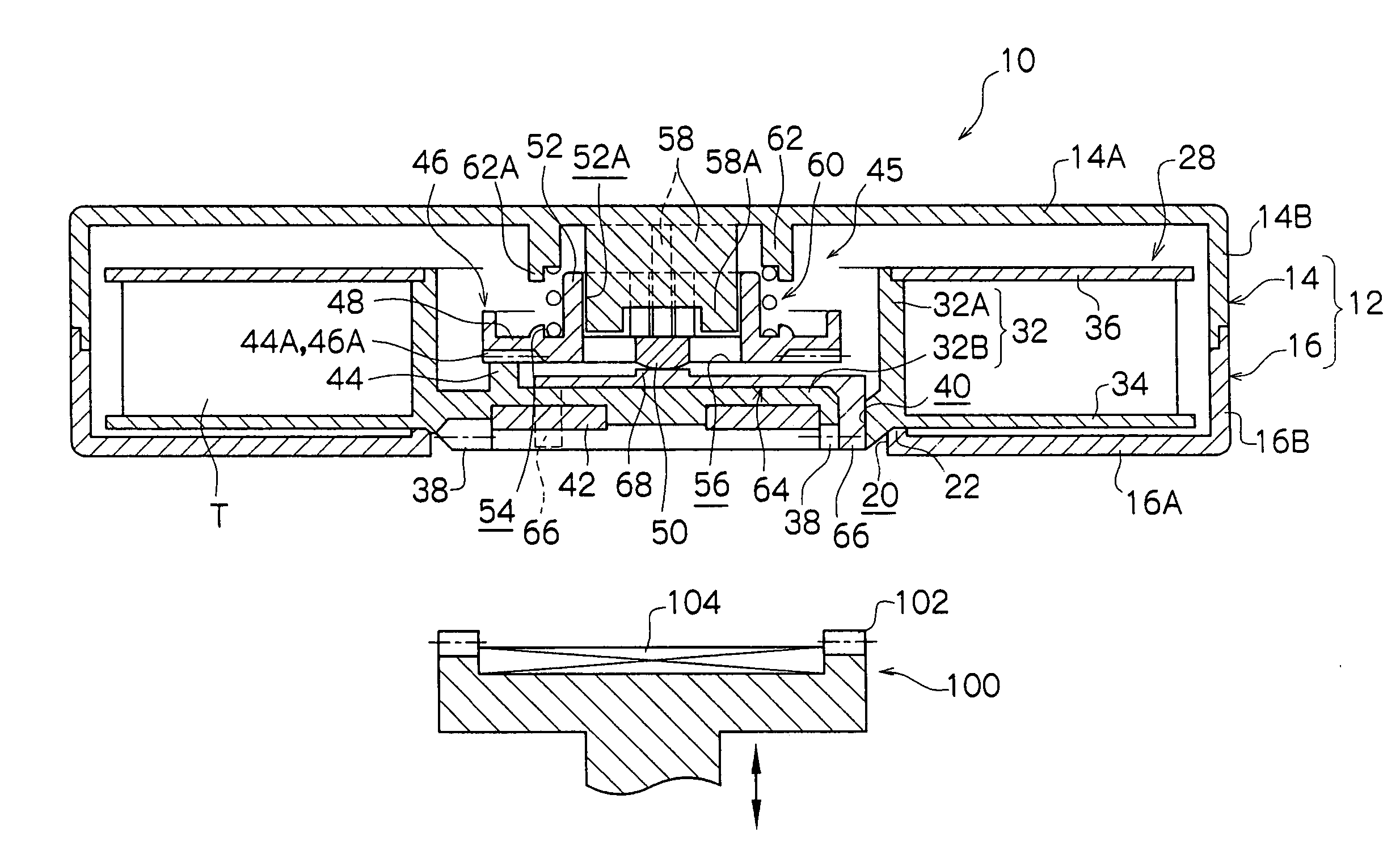
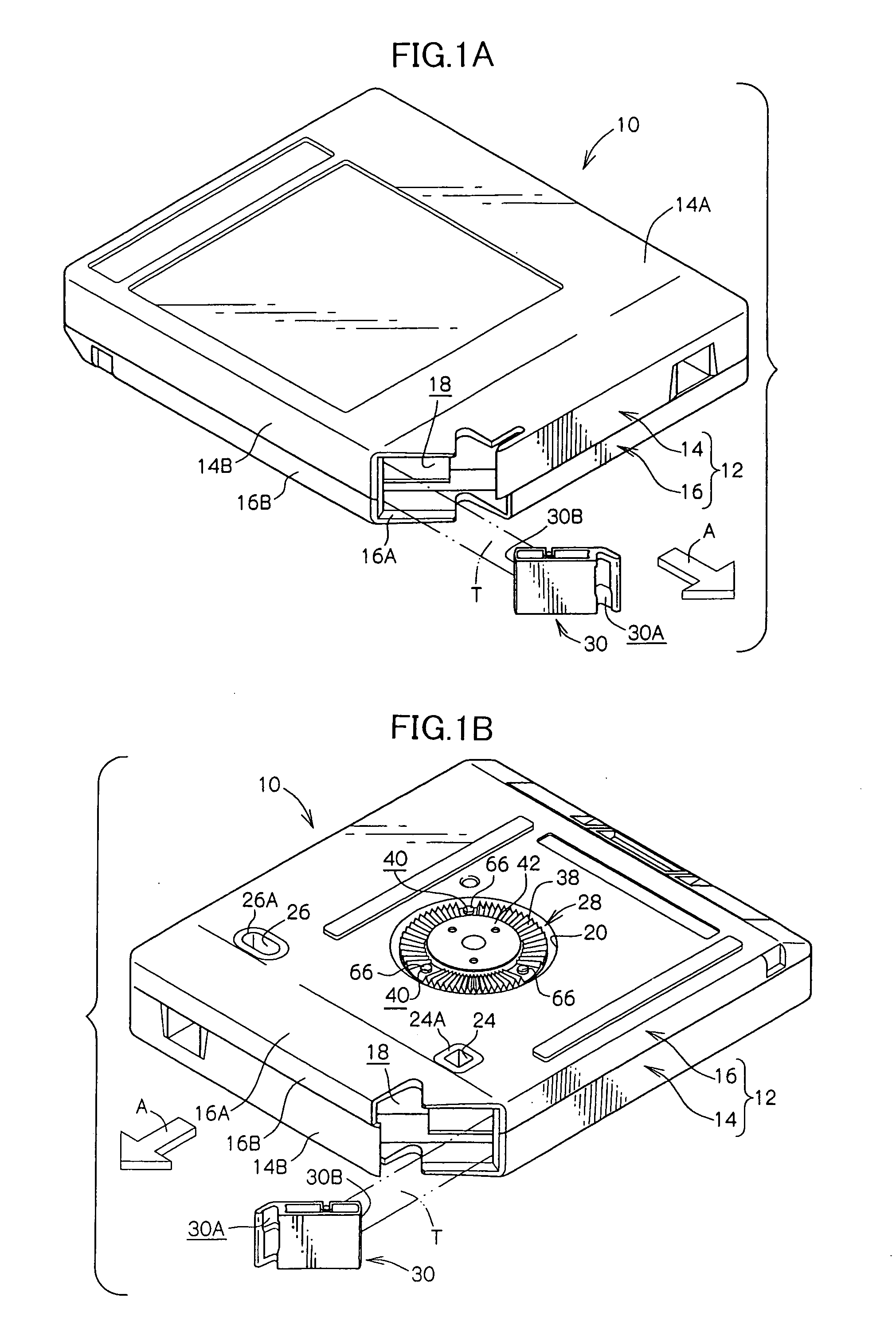
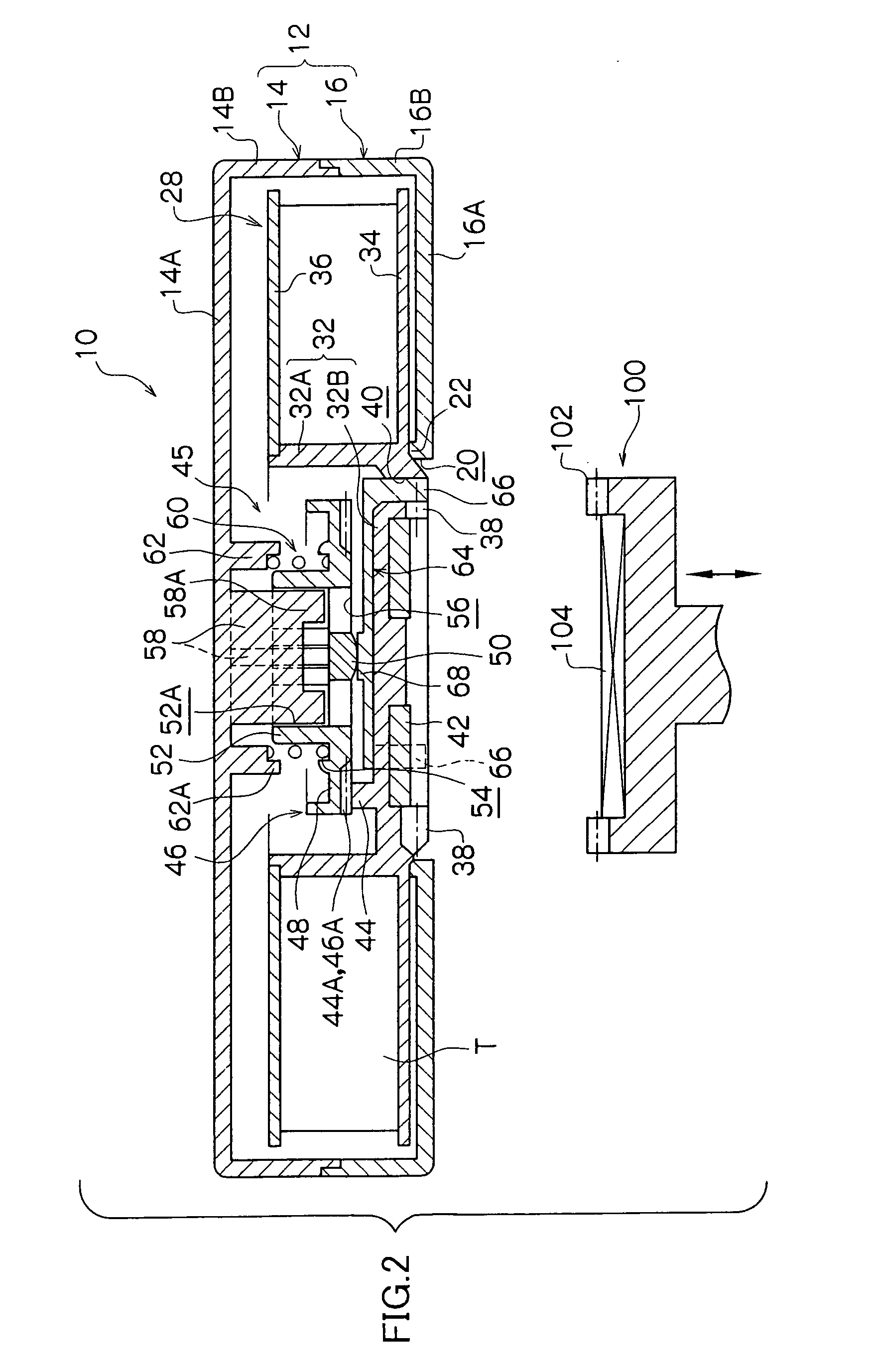
[0053]FIG. 1A is a perspective view showing the recording tape cartridge 10 as seen obliquely from above, and FIG. 1B is a perspective view of the recording tape cartridge 10 as seen obliquely from below. FIG. 2 is a cross-sectional view of the recording tape cartridge 10. An arrow A shown in FIG. 1 indicates a loading direction of the recording tape cartridge 10 into a drive device. For descriptive convenience, a side indicated by the arrow A is defined as the front side.

[0054] As illustrated in these figures, the recording tape cartridge 10 includes a case 12. The case 12 is formed by joining an upper case 14 and a lower case 16 to each other. More specifically, the upper case 14 is formed such that a generally frame-shaped peripheral wall 14B is provided upright along the edge of a ...


PUM

PropertyMeasurementUnit
lengthaaaaaaaaaa
lengthaaaaaaaaaa
diameteraaaaaaaaaa

Abstract

A recording tape cartridge is disclosed wherein when in non-use, a reel accommodated in a case and having a recording tape wound thereon is prevented from rotating by being meshed with a braking member which is non-rotatble with reference to the case; and when in use, in response to the braking member being pushed up by a release pad or a clutch member, the reel is released from the meshed state and allowed to rotate together with the release pad or the clutch member. With the rotation of the reel, the braking member has its pivot portion disposed in sliding contact with a sliding contact portion formed at a portion corresponding to an axial center of the release pad or the clutch member while being pressed against the sliding contact portion by a biasing force of a compression coil spring. The recording tape cartridge is designed such that a relation μ×L≦0.4 holds between a length L (mm) of the compression coil spring along the axis line of the reel when the reel rotates together with the release pad or the clutch member and a coefficient of dynamic friction μ between the pivot portion of the braking member and the sliding contact portion of the release pad or the clutch member.

Description

CROSS-REFERENCE TO RELATED APPLICATION [0001] This application claims priority under 35 USC 119 from Japanese Patent Application No. 2003-411146, the disclosure of which is incorporated by reference hereinBACKGROUND OF THE INVENTION [0002] 1. Field of the Invention [0003] The present invention relates to a recording tape cartridge which rotatably accommodates a reel on which a recording tape such as a magnetic tape or the like is wound. [0004] 2. Description of the Related Art [0005] A recording tape such as a magnetic tape is used as an external recording medium for a computer or the like, and a so-called 1-reel recording tape cartridge is employed which rotatably accommodates a single reel of a recording tape. Advantageously, this type of recording tape cartridge requires only a small storage space and yet is capable of recording a large amount of information. [0006] Such a recording tape cartridge includes a lock mechanism, which prevents a reel from being rotated when the record...

Claims


Application Information

Patent Timeline
Patent Type & Authority Applications(United States)
IPC IPC(8): G11B15/32G11B23/04G11B23/107
CPCG11B23/107G11B23/043
Inventor ISHIKAWA, REN
Owner FUJIFILM CORP
Why Eureka
Try Eureka