Image scanning device

a scanning device and image technology, applied in the field of image scanning devices, can solve the problems of high accuracy and high cost, and achieve the effects of reducing the number of components, simplifying configuration, and enhancing support accuracy

Inactive Publication Date: 2011-07-21
MURATA MASCH LTD
View PDF5 Cites 5 Cited by
  • Summary
  • Abstract
  • Description
  • Claims
  • Application Information

AI Technical Summary

Benefits of technology

[0017]In this device, the scanning carriage can take in the document image while being proximate to the platen glass when the scanning carriage travels through the first portion of the side wall guide groove. Furthermore, the scanning carriage can take in the document image while being proximate to the slit glass when the scanning carriage is positioned at the third portion of the side wall guide groove. Moreover, the scanning carriage moves to the lower side than the image scanning position when passing through the second portion of the side wall guide groove. Therefore, the scanning carriage is less likely to collide against the supporting member even if the image scanning position of the scanning carriage is relatively high.
[0018]The side wall guide groove may preferably be integrally molded with the housing, for example. In this device, the number of components is reduced and the configuration is simplified.
[0019]The image scanning device may further include a bottom surface guide groove arranged at the bottom surface of the housing to guide the scanning carriage in the scanning direction. In this device, the supporting accuracy is further enhanced since the scanning carriage is guided by the bottom surface guide groove, and as a result, the scanning carriage can stably travel.
[0020]In the image scanning device according to various preferred embodiments of the present invention, the scanning carriage is guided with a simple structure while maintaining a sufficient accuracy.

Problems solved by technology

When the guide shaft is used as a mechanism for supporting the carriage as in JP-A-2006-197419, the cost becomes expensive since high accuracy is demanded.

Method used


Image

  • Image scanning device
  • Image scanning device
  • Image scanning device

Examples


Embodiment Construction

(1) Copy / Facsimile Multifunction Peripheral

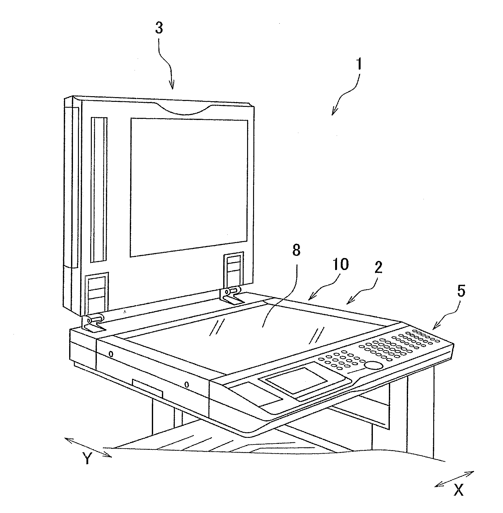
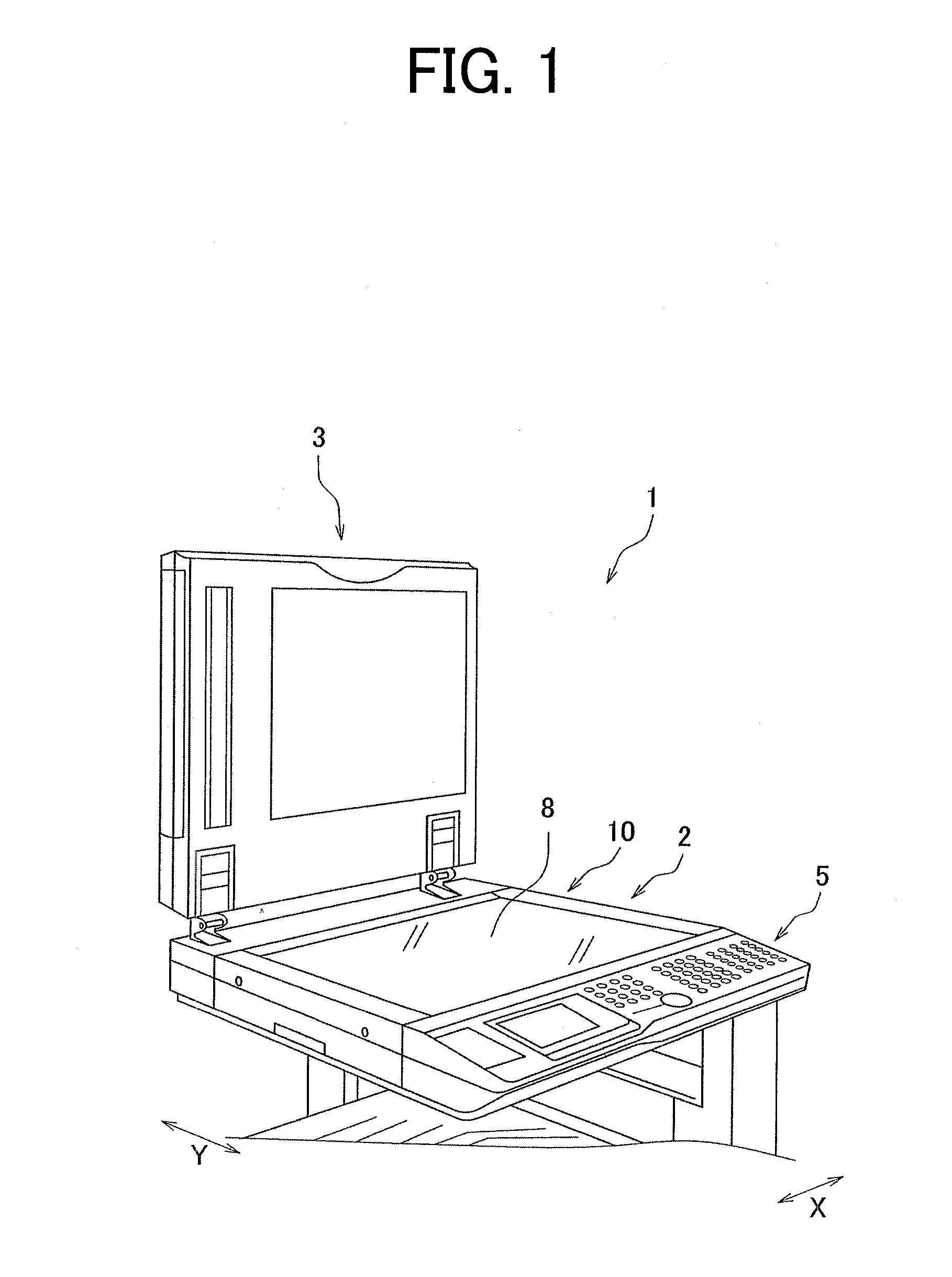
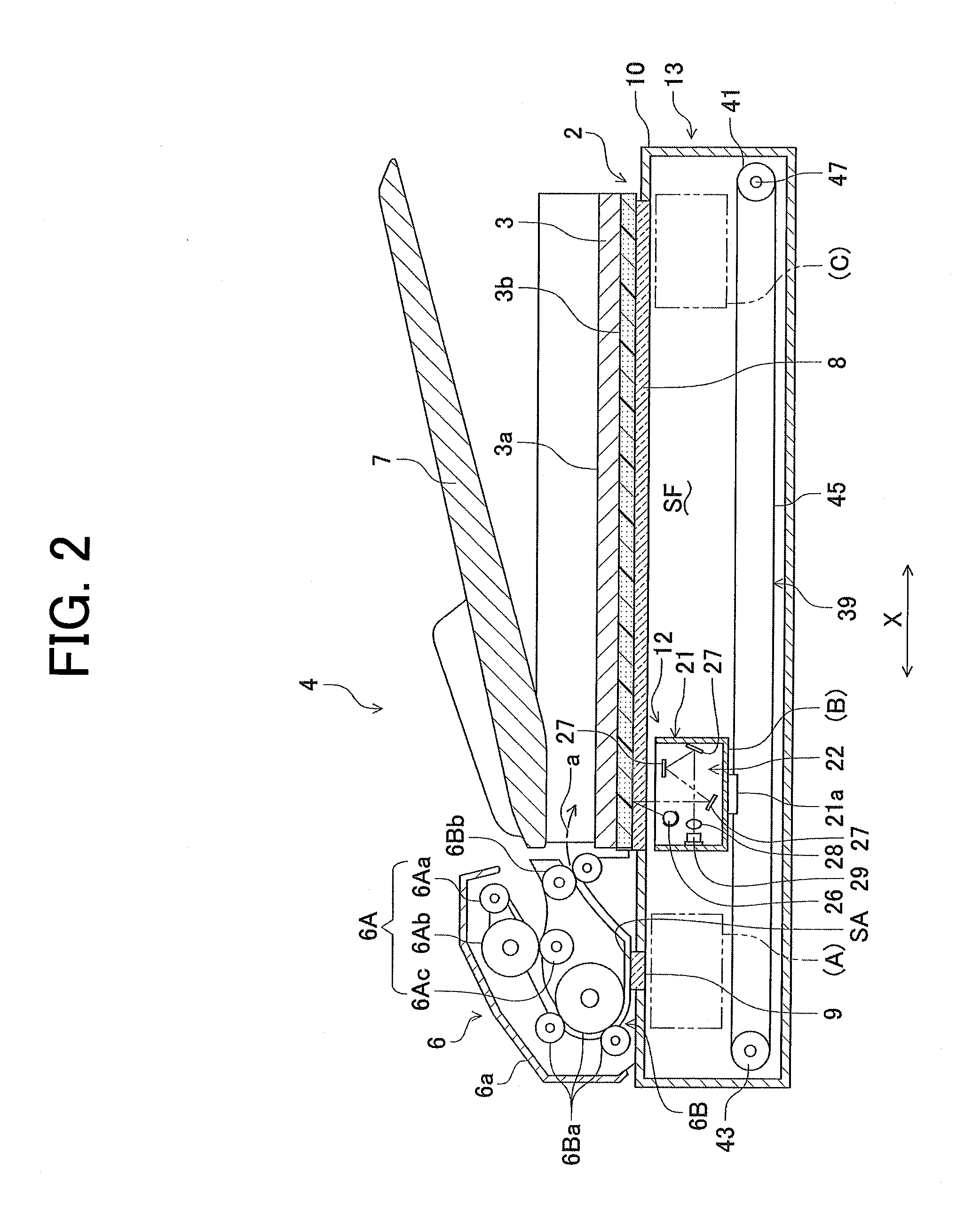
[0033]A copy / facsimile multifunction peripheral 1 will be described with reference to FIGS. 1 and 2. FIG. 1 is a perspective view of an outer appearance of an upper portion of a copy / facsimile multifunction peripheral 1 including an image scanning device according to a preferred embodiment of the present invention. FIG. 2 is a cross-sectional view of the upper portion of the copy / facsimile multifunction peripheral.

[0034]Hereinafter, the left and right direction of the device (belt extending direction, and scanning direction of carriage) is referred to as an “X-direction”, and the front and back direction of the device is referred to as a “Y-direction”. The X-direction and the Y-direction are perpendicular or substantially perpendicular to each other.

[0035]The copy / facsimile multifunction peripheral 1 includes a scanning table 2 serving as a Flat Bed Scanner (FBS), and a document pressing cover 3 attached to the scanning table 2 in a freely ...


PUM


Abstract

An image scanning device includes a housing, a scanning carriage, and a first guide groove and a second guide groove. The housing includes a bottom chassis and a side wall member, and defines a document tray. A scanning carriage is movably arranged in the housing. The first guide groove and the second guide groove are arranged at the side wall members of the housing, and guide the scanning carriage in a scanning direction.

Description

[0001]This application claims priority under 35 U.S.C. 119 to Japanese Patent Application Nos. 2010-7836, filed on Jan. 18, 2010 and 2010-218751 filed on Sep. 29, 2010, which applications are hereby incorporated by reference in their entirety.BACKGROUND OF THE INVENTION[0002]1. Field of the Invention[0003]The present invention relates to image scanning devices, and in particular, to an image scanning device including a scanning carriage.[0004]2. Description of the Related Art[0005]Some scanners, facsimiles, copy machines, and the like use a flat bed scanner (hereinafter referred to as “FBS”) in which a scanning unit of a reduction optical system such as a Charge Coupled Device (CCD) is incorporated in a scanning table as an image scanning unit.[0006]In JP-A-2006-197419, an image scanning device 1 includes a carriage 20. A guide shaft 22 extending along the scanning direction is arranged on one side of a scanning range of the carriage 20. The guide shaft 22 is inserted into a guide h...

Claims


Application Information

Patent Timeline
Patent Type & Authority Applications(United States)
IPC IPC(8): H04N1/04
CPCH04N1/00559H04N1/1017H04N1/1035H04N1/12H04N2201/0446H04N2201/0081H04N2201/02404H04N2201/0442H04N1/193
Inventor OTSUKI, OSAMU
Owner MURATA MASCH LTD
Why Eureka
Try Eureka