Variable capacitor employing MEMS technology

a variable capacitor and capacitor technology, applied in the field of variable capacitors, can solve the problems of difficult to make common passive components such as capacitors and inductors, and increasing the number of components, along with the increase of the frequency band

Active Publication Date: 2011-10-18
LAPIS SEMICON CO LTD
View PDF8 Cites 25 Cited by
  • Summary
  • Abstract
  • Description
  • Claims
  • Application Information

AI Technical Summary

Benefits of technology

[0015]A first aspect of the present invention is a variable capacitor including: a support substrate; a first electrode formed as a thin film on a surface of the support substrate; a flat plate shaped second electrode provided in a fixed position above the first electrode and provided with plural comb teeth portions projecting out toward the first electrode; a flat plate shaped third electrode disposed between the first electrode and the second electrode, the third electrode retained so as to be movable with respect to the second electrode in a vertical direction and a horizontal direction, provided with plural comb teeth portions facing toward spaces between the plural comb teeth portions of the second electrode and projecting out toward the second electrode, the surface of the third electrode covered in a dielectric layer, wherein a variable capacitor is configured by the third electrode and the second electrode, and the third electrode moves in a vertical direction according to a first voltage applied between the first electrode and the second electrode; a flat plate shaped fourth electrode disposed in a fixed position above the first electrode, the fourth electrode being connected in the horizontal direction to the second electrode, provided with plural comb teeth portions projecting out toward the first electrode, and being electrically insulated from the second electrode; a flat plate shaped fifth electrode disposed between the first electrode and the fourth electrode, the fifth electrode being connected in a horizontal direction to the third electrode and provided with at least one comb tooth portion facing toward a space between the plural comb teeth portions of the fourth electrode and projecting out toward the fourth electrode, the surface of the fifth electrode being covered in a dielectric layer, the fifth electrode configuring with the fourth electrode a vibration prevention portion that prevents vibration of the third electrode, the fifth electrode moving in a horizontal direction according to a second voltage applied between the fourth electrode and the fifth electrode with the comb teeth portions of the fourth electrode and the comb teeth portion(s) of the fifth electrode making contact and fixing the fifth electrode to the fourth electrode due to frictional force.
[0016]A second aspect of the present invention is a variable capacitor including: a support substrate; a first electrode formed as a thin film on a surface of the support substrate; a flat plate shaped second electrode provided in a fixed position above the first electrode and provided with plural comb teeth portions projecting out toward the first electrode; a flat plate shaped third electrode disposed between the first electrode and the second electrode, the third electrode retained so as to be movable with respect to the second electrode in a vertical direction and a horizontal direction, provided with plural comb teeth portions facing toward spaces between the plural comb teeth portions of the second electrode and projecting out toward the second electrode, with the surface of the third electrode covered in a dielectric layer, wherein a variable capacitor is configured by the third electrode and the second electrode, and the third electrode moves in a vertical direction according to a first voltage applied between the first electrode and the second electrode; plural pairs of flat plate shaped fourth electrodes disposed in a fixed position above the first electrode, connected in the horizontal direction to the second electrode so as to be left-right symmetrical with respect to the second electrode, provided with plural comb teeth portions projecting out toward the first electrode, and electrically insulated from the second electrode; plural flat plate shaped fifth electrodes, provided so as correspond to each of the plural pairs of fourth electrodes, disposed between the first electrode and the fourth electrodes, connected to the third electrode in a horizontal direction, and each provided with at least one comb tooth portion facing toward a space between the plural comb teeth portions of the respective fourth electrode and projecting out toward the fourth electrode, the surface of the fifth electrodes covered in a dielectric layer, the fifth electrodes configuring with each of the respective plural pairs of fourth a vibration prevention portion that prevents vibration of the third electrode, each of the respective fifth electrodes in a pair moving in opposite horizontal directions according to a second voltage applied between the fourth electrodes and the fifth electrodes, with the comb teeth portions of the fourth electrodes and the comb teeth portions of the fifth electrodes making contact and fixing the fifth electrodes to the respective of the plural pairs of fourth electrodes due to frictional force.

Problems solved by technology

The problem with this is the increase in the number of components.
In particular it is difficult to make common passive components such as capacitors and inductors, and so the number of components increases along with the increase in the number of frequency bands.
As the number of components increases problems arise in that the volume of the RF front end becomes large and there the const becomes expensive.
However, a problem arises in that these variable capacitors are not capable of stably maintaining the position of the moveable electrode after movement.
The electrostatic capacitance changes if the position of the moveable electrode changes due to external vibration, leading to problems of unstable operation.
Consequently, there is concern of short circuiting occurring if external vibration is imparted during operation and the fixed electrode and the moveable electrode make contact with each other.

Method used


Image

  • Variable capacitor employing MEMS technology
  • Variable capacitor employing MEMS technology
  • Variable capacitor employing MEMS technology

Examples


first exemplary embodiment

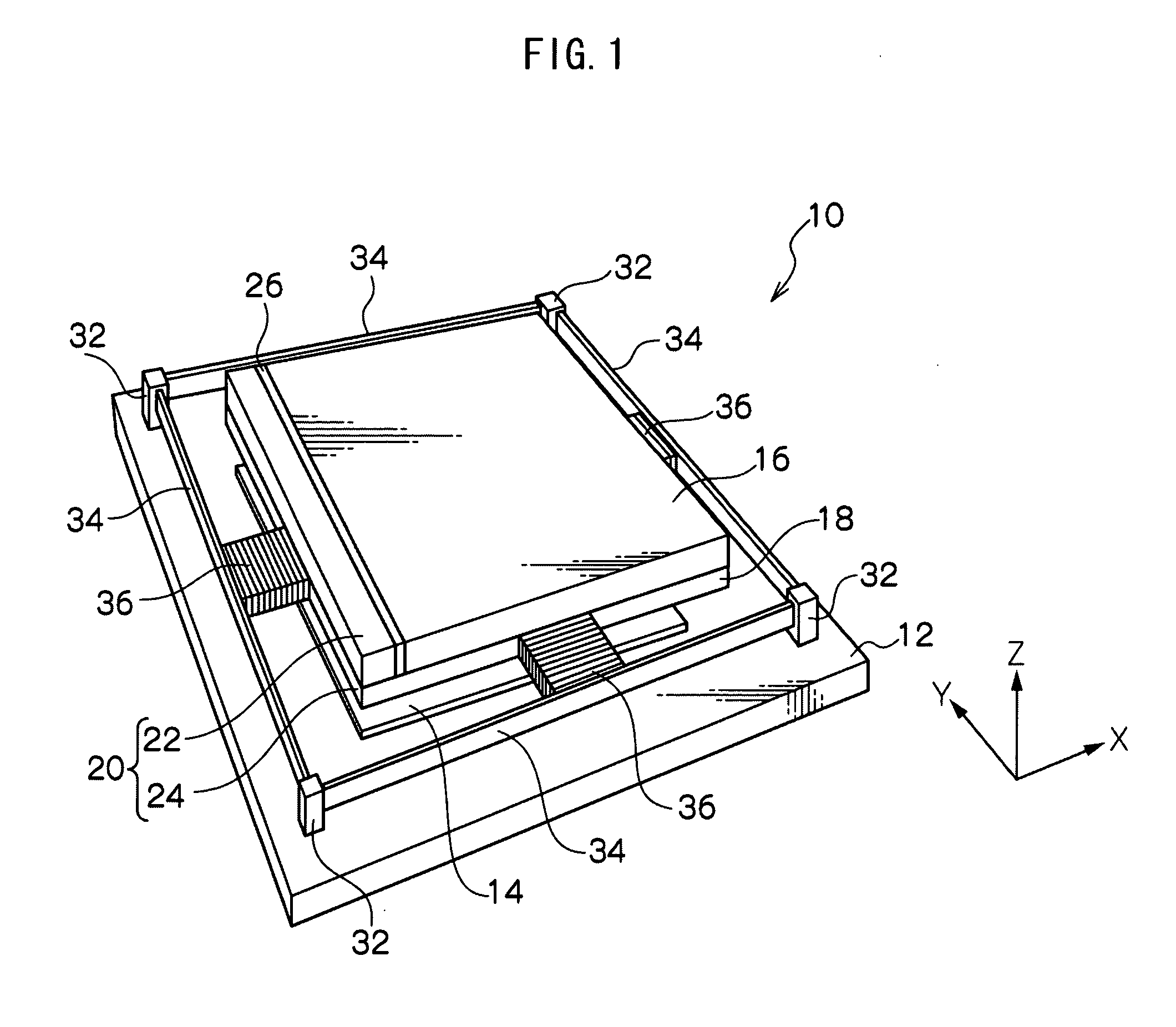
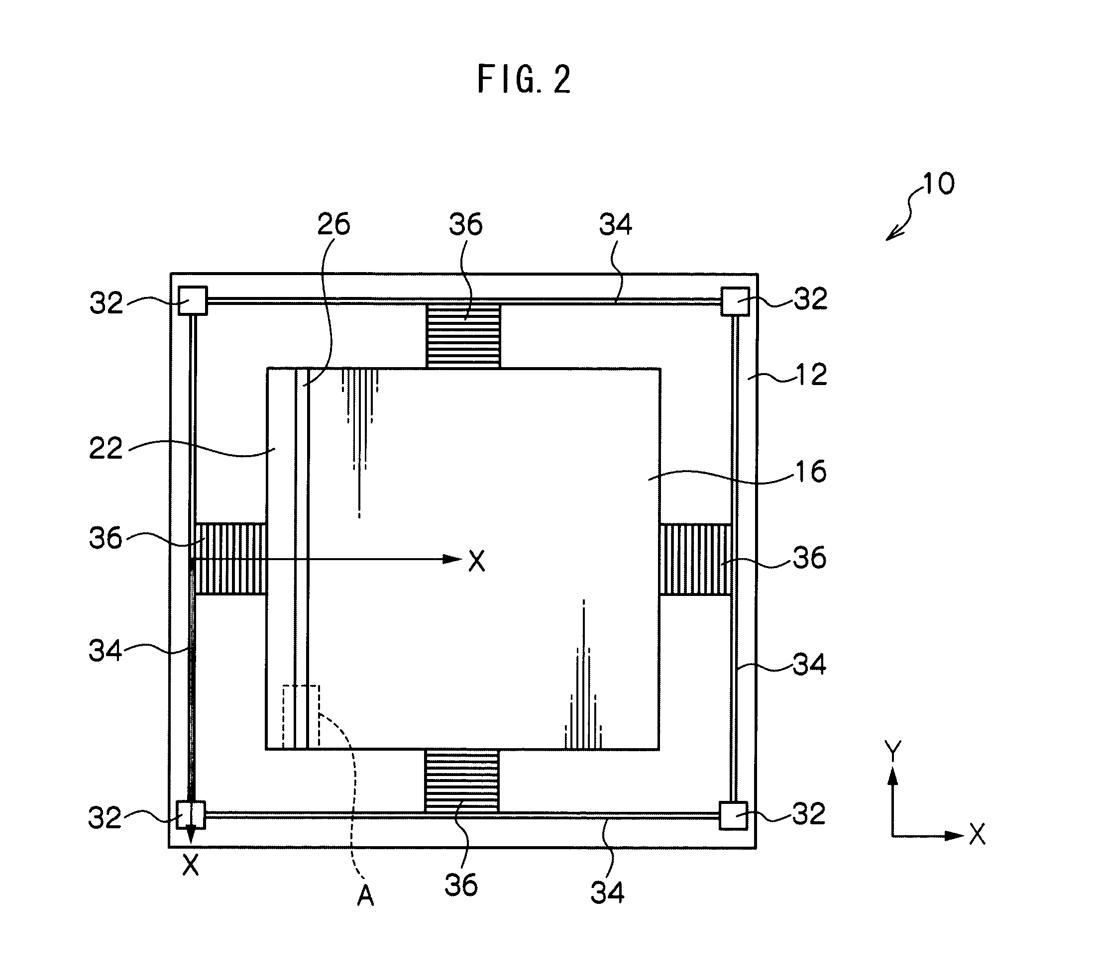
[0053]Outline Configuration of Variable Capacitor

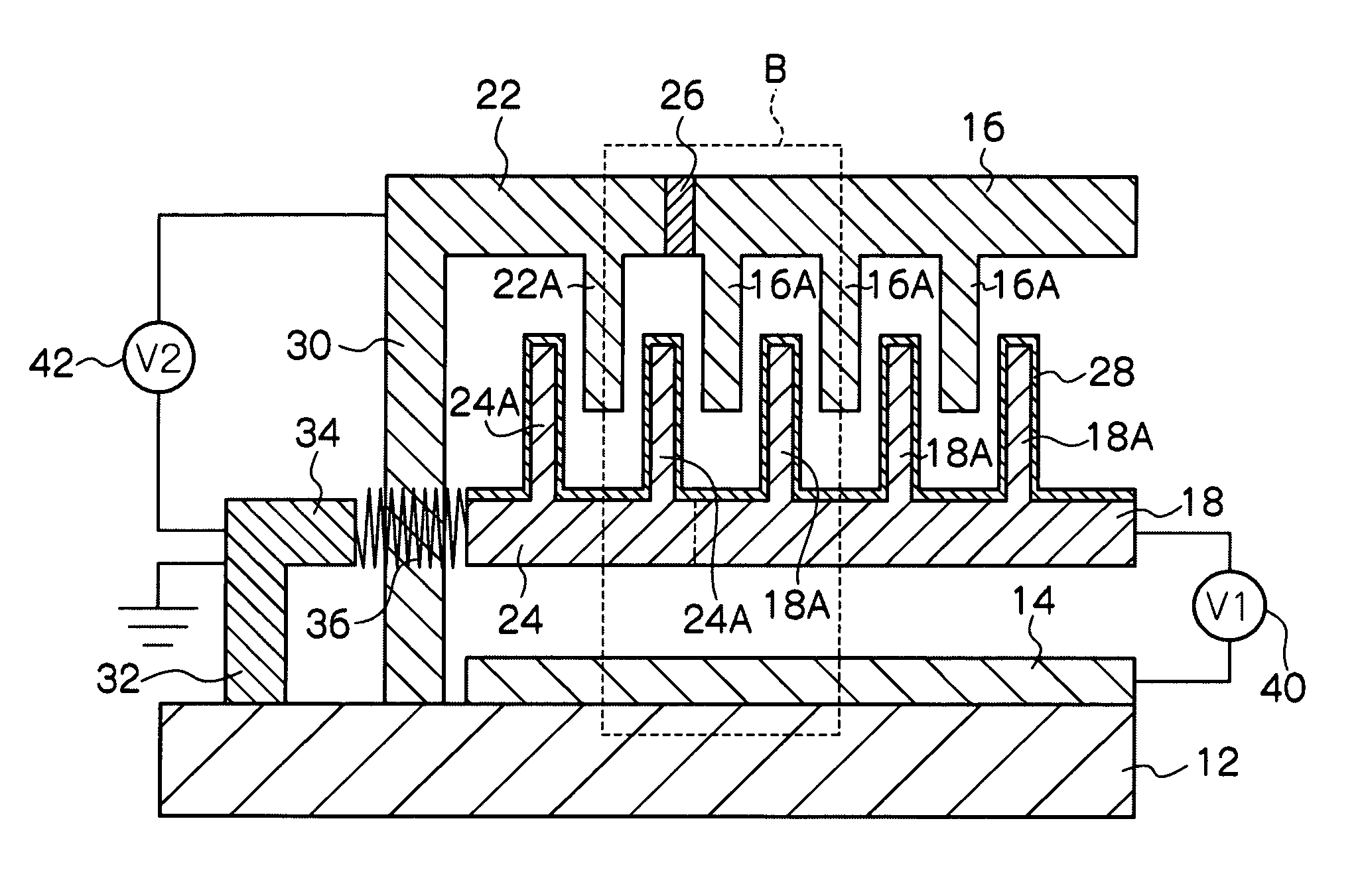
[0054]First, a simple explanation will be given of a configuration of a variable capacitor, with reference to FIG. 1 to FIG. 3. FIG. 1 is a perspective view showing the external appearance of a variable capacitor according to a first exemplary embodiment of the present invention. FIG. 2 is a plan view of a variable capacitor, as seen from the fixed electrode. FIG. 3 is a side view of a variable capacitor.

[0055]A variable capacitor 10 is equipped with: a support substrate 12 configured from a semiconductor such as silicon or the like; a drive electrode 14 disposed on the support substrate 12; a fixed electrode 16 disposed so as to face the drive electrode 14 with a separation therebetween; a movable electrode 18, disposed retained moveably between the drive electrode 14 and the fixed electrode 16; and a brake capacitor 20, serving as a vibration prevention portion for preventing vibration after movement of the movable electrode 18. The...

second exemplary embodiment

[0119]FIGS. 14A to 14C are enlarged diagrams of portions of a variable capacitor according to a second exemplary embodiment of the present invention. FIG. 14A is a diagram corresponding to FIG. 6 of the first exemplary embodiment. A variable capacitor 10A according to the second exemplary embodiment is of similar configuration to that of the first exemplary embodiment, except in that a movable drive electrode 52 is formed to the back face of the movable electrode 18 to which the lower portion brake electrode 24 is attached, with an insulating layer 50 interposed therebetween. Therefore similar portions will be allocated the same reference numerals and part of the explanation thereof will be omitted.

[0120]As shown in FIG. 14A, a movable electrode 18 and a lower portion brake electrode 24 are integrally formed from an electrically-conductive material, as a member of rectangular shape in plan view. The portion of this member facing a fixed electrode 16 is the movable electrode 18, and ...

third exemplary embodiment

[0141]FIG. 17 is a side view of a variable capacitor according to a third exemplary embodiment of the present invention. FIGS. 18A to 18C are enlarged diagrams of portions of a variable capacitor according to the third exemplary embodiment of the present invention. FIG. 17 is a diagram corresponding to FIG. 3 of the first exemplary embodiment. FIG. 18A is a diagram corresponding to FIG. 6 of the first exemplary embodiment. A variable capacitor 10B according to the third exemplary embodiment is of similar configuration to that of the first exemplary embodiment, except in that a dielectric layer 60 is provided on the support substrate 12 so as to cover the drive electrode 14. Therefore similar portions will be allocated the same reference numerals and part of the explanation thereof omitted

[0142]In a similar manner to in the first exemplary embodiment, a drive electrode 14 of a rectangular shape in plan view that is slightly smaller than a support substrate 12, is formed at the middle...


PUM


Abstract

When a positive voltage of V1 is applied to a drive capacitor with a braking voltage V2 at 0V, a moveable electrode moves toward the drive electrode, and a capacitance C of a tunable capacitor becomes smaller. When the braking voltage V2 is applied a lower portion brake electrode of the brake capacitor moves in a horizontal direction, such that the inter electrode separation distance between an upper portion brake electrode and the lower portion brake electrode becomes 0 μm. The moveable electrode configured integrally formed with the lower portion brake electrode also moves in the horizontal direction, and the inter electrode separation distance between the moveable electrode and a fixed electrode becomes 0 μm. Since the two electrodes make contact with each other with a dielectric layer interposed therebetween, the position of the moveable electrode can be stably maintained by frictional force between the electrodes.

Description

CROSS-REFERENCE TO RELATED APPLICATION[0001]This application is based on and claims priority under 35 USC 119 from Japanese Patent Application No. 2008-208584 filed on Aug. 13, 2008, the disclosure of which is incorporated by reference herein.BACKGROUND[0002]1. Technical Field[0003]The present invention relates to a variable capacitor, and in particular to a variable capacitor employing MEMS (Micro Electro Mechanical System) technology.[0004]2. Related Art[0005]Recently there has been significant progress in wireless communication equipment, typified by mobile phones. The next generation of mobile phones will use multiple frequency bands. This has lead to progress in the development of multi-frequency receivable RF (Radio Frequency) front ends. The problem with this is the increase in the number of components. In particular it is difficult to make common passive components such as capacitors and inductors, and so the number of components increases along with the increase in the numb...

Claims


Application Information

Patent Timeline
Patent Type & Authority Patents(United States)
IPC IPC(8): H01L29/00
CPCH01G5/011H01G5/18
Inventor NI, WEI
Owner LAPIS SEMICON CO LTD
Why Eureka
Try Eureka