Method and system for identification of changes in fluids

a fluid and change technology, applied in the field of fluid examination, can solve the problems of complex methods, recording and measuring images, and sophisticated calculations, and achieve the effects of simple, cheap and reliable optical systems, easy identification, and high distinguishability

Inactive Publication Date: 2011-10-18
QUALISENSE TECH
View PDF4 Cites 2 Cited by
  • Summary
  • Abstract
  • Description
  • Claims
  • Application Information

AI Technical Summary

Benefits of technology

[0018]c) an optical system having an optical axis and enabling the observation of the object when illuminated by diffuse light, via the enclosure filled with said fluid.
[0027]In the above specific example, the two lenses of the enclosure are selected such that the whole enclosure has optical power close to zero when filled with the fluid in the reference state, so that an infinite fringe (i.e. no moiré pattern), which is observed in that state, constitutes the predetermined reference image. When the state of the fluid changes, the refraction index changes as well and a moiré pattern distinguishable by the viewer is obtained. This is the changed image which is easy to be identified visually or by a sensor.
[0029]Contrary to methods of measurement, the designer of the optical arrangement implementing the method of the invention has previous knowledge of the optical parameter both in the reference state and in the changed state of the fluid, so that he can design his system accordingly to make the changed state of the fluid highly distinguishable. Therefore, the arrangement may be adjusted for easy identification of a small change of the optical parameter without measuring it.

Problems solved by technology

Such methods require relatively complex optical systems, recording and measurement of images and sophisticated calculations in order to determine accurately a change in the optical parameter of the liquid.

Method used


Image

  • Method and system for identification of changes in fluids
  • Method and system for identification of changes in fluids
  • Method and system for identification of changes in fluids

Examples


Embodiment Construction

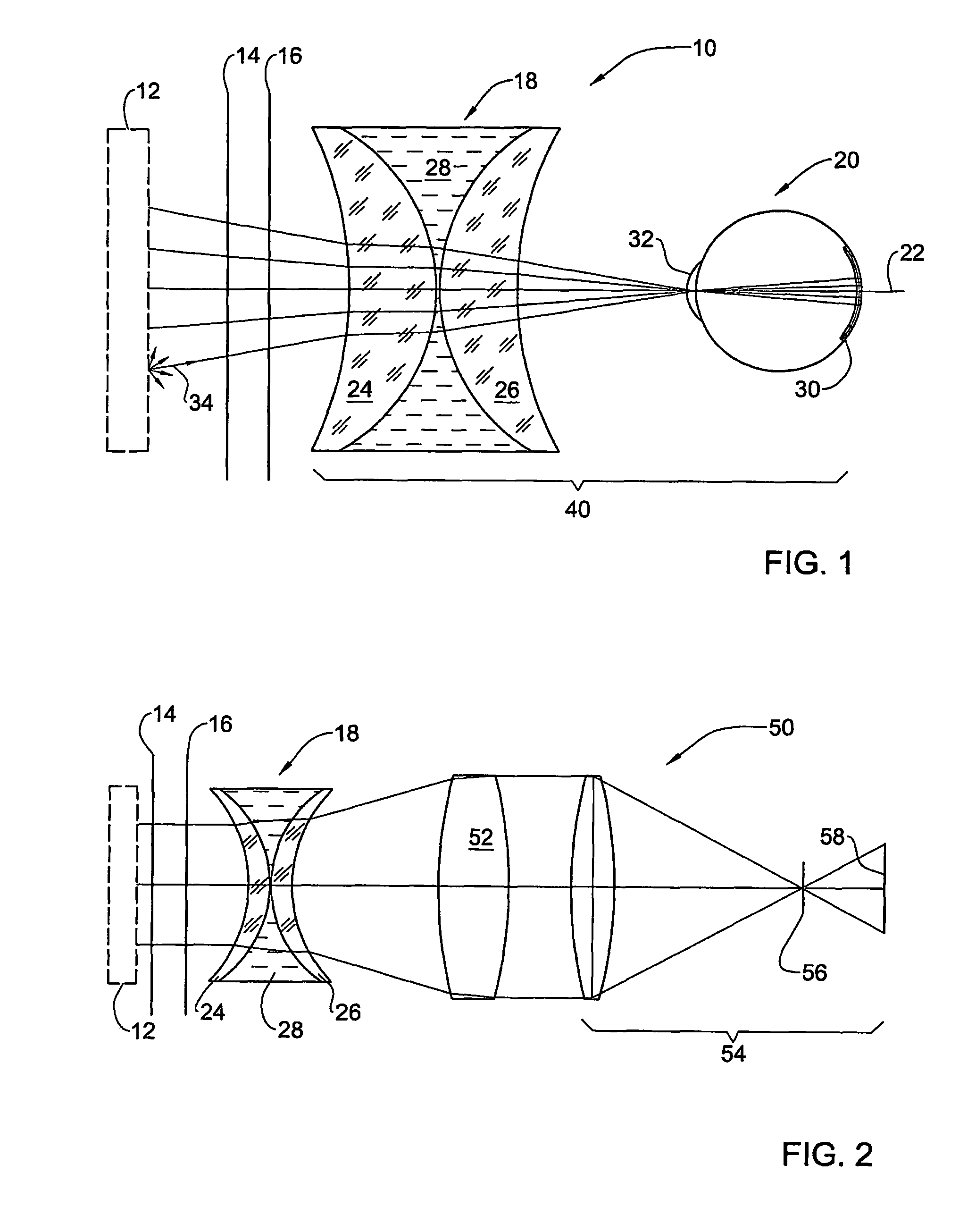
[0037]With reference to FIG. 1, there is schematically shown one example of an optical arrangement 10 in accordance with the present invention. The optical arrangement comprises two gratings 14 and 16 that may be illuminated by ambient light or by a light from a diffuse light source 12 which, being optional, is shown in dotted lines. The arrangement 16 further comprises a transparent enclosure (cuvette) 18 with an axis coinciding with the direction of observation 22 via the enclosure 18 of the gratings 14 and 16, by the eye 20 of the observer.

[0038]The source 12 may be any common fluorescent or incandescent lamp. The gratings 14, 16 are common Ronchi rulings with identical period. The cuvette 18 is built of two concave-convex lenses 24, 26, whose convex faces are almost touching. A cavity 28 formed between the lenses is adapted to be filled with a liquid to be monitored. The liquid may be any liquid whose state changes in time. The liquid's original state is considered to be a refer...


PUM

PropertyMeasurementUnit
Talbot distanceaaaaaaaaaa
refraction indexaaaaaaaaaa
transparentaaaaaaaaaa

Abstract

Method and system for identification of a changed state of a fluid with respect to a reference state of the same fluid, the fluid having an optical parameter changing with the change of the state of the fluid. The method comprises: a) providing an optical arrangement including a transparent enclosure with a portion of the fluid, and an object observable through the optical arrangement, the arrangement being designed such that an image of the object in the changed state of the fluid is optically distinctive from an image of the object in the reference state of the fluid due to change of the optical parameter, at least one of the images being predetermined; b) illuminating the object with diffuse light; c) observing a current image of the object though the optical arrangement along an optical axis; and d) comparing the current image to the predetermined image to identify the changed state of the fluid. The comparison and the identification may be performed by eye or by a sensor with a logical circuit.

Description

FIELD OF THE INVENTION[0001]This invention relates to the examination of fluids based on their optical properties.BACKGROUND OF TEE INVENTION[0002]There exist systems for measuring optical properties of fluids. U.S. Pat. No. 4,569,590 to Karney describes a system for determining unknown index of refraction of a sample fluid with reference to the refraction index of a known reference fluid. The system comprises a collimated light source, a light pervious cell formed as a biconvex lens fillable with a fluid, a pair of gratings and a screen. Collimated light is directed through the cell filled first with the reference fluid and then with the sample fluid, onto the gratings, and reference and sample patterns are obtained thereby on the screen. The sample pattern will be different from the reference one if the optical power of the biconvex lens changes due to the change of the liquid in the cell. The difference between the reference pattern and the sample pattern is then measured and use...

Claims


Application Information

Patent Timeline
Patent Type & Authority Patents(United States)
IPC IPC(8): G01N21/41G01N21/45
CPCG01N21/45
Inventor GAN, LIVNE
Owner QUALISENSE TECH
Why Eureka
Try Eureka