
Method for filtering noises in optical parametric chirped-pulse amplifier and device therefor

a technology of optical parametric chirped-pulse amplifier and filtering method, which is applied in optics, instruments, electromagnetic transmission, etc., can solve the problems of difficult filtering noise that grows during amplification, bottlenecks, and difficulty in enhancing contrast, etc., and achieves poor temporal contrast

Active Publication Date: 2015-10-08
SHANGHAI JIAO TONG UNIV
View PDF0 Cites 3 Cited by
  • Summary
  • Abstract
  • Description
  • Claims
  • Application Information

AI Technical Summary

Benefits of technology

The present invention provides a method for filtering out noises that grow during parametric amplification in optical parameter chirped-pulse amplifiers. By introducing spatial chirp into the seed beam before amplification and removing it after amplification using a compressor, the noises that have temporal and spatial chirp can be effectively filtered out. This method is efficient and simple and can be applied to all three kinds of noises in optical parameter chirped-pulse amplifiers.

Problems solved by technology

This contrast bottleneck arises as a combined result of the seed pulse's quality, noises from amplification and imperfections in stretcher and compressor.
Contrast enhancement is always one of the most difficult problems in high peak-power laser engineering and application.
The difficulty of filtering noises that grow during amplification comes from the fact that the noises and signal usually overlap each other in all of the spatial, temporal and spectral domains.
Despite the noises present different temporal structures with the main pulse after compression, there is so far no efficient temporal filtering technology with controlled switching time at femtosecond scale.
The nonlinear temporal domain filtering technologies that have been used in cleaning seed pulses such as cross-polarized wave generation, are not applicable at the end of the amplifier due to the low energy conversion efficiencies of 10%-30%.

Method used


Image

  • Method for filtering noises in optical parametric chirped-pulse amplifier and device therefor
  • Method for filtering noises in optical parametric chirped-pulse amplifier and device therefor
  • Method for filtering noises in optical parametric chirped-pulse amplifier and device therefor

Examples


Embodiment Construction

[0026]The present invention is further described according to a group of numerical simulation results.

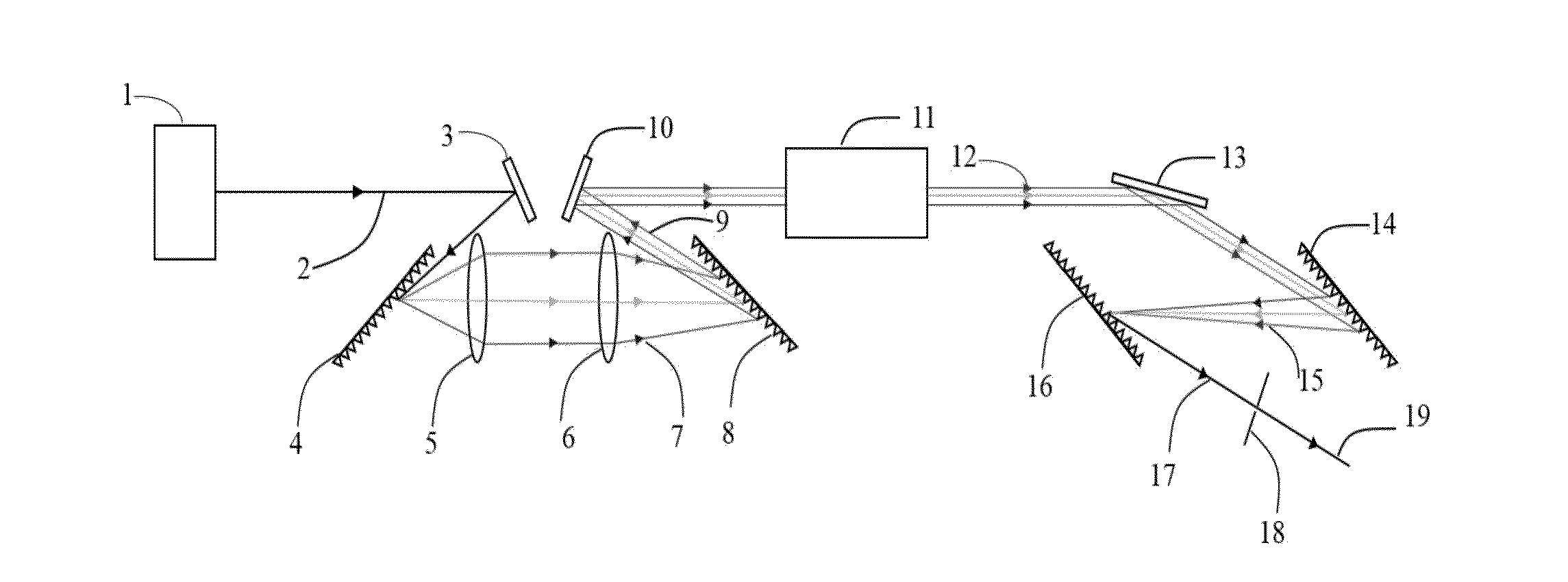
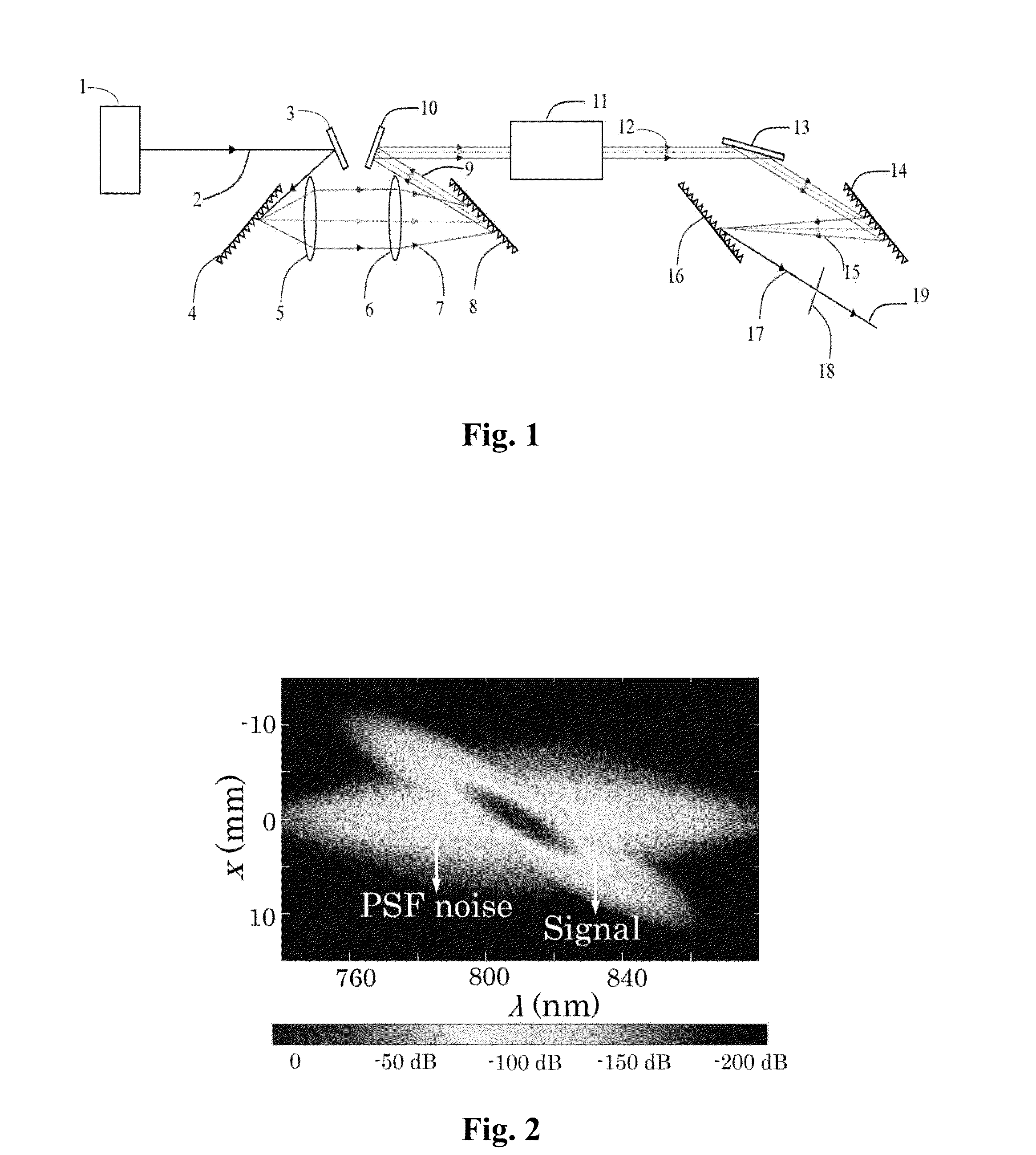
[0027]FIG. 1 shows a schematic view of a device using a method of spatial-chirp-dressed seed beam and near-filed noise filtering in an optical parametric chirped-pulse amplifier. The method comprises steps of: generating a seed beam dressed with spatial chirp, conducting optical parametric amplification, removing temporal and spatial chirp, and filtering noise in spatial domain.

[0028]Ultrashort seed pulse 2 emitted by ultrashort pulsed-laser source 1 is reflected by first reflector 3 to first grating in stretcher 4. After being diffracted by first grating in stretcher 4, ultrashort seed pulse 2 acquires an angular dispersion. Group-velocity dispersion is introduced when the pulse propagates away from first grating in stretcher 4 and transit-time dispersion increases with the propagation. When the desired dispersion is achieved after the pulse passing through first imaging lens 5 and...


PUM


Abstract

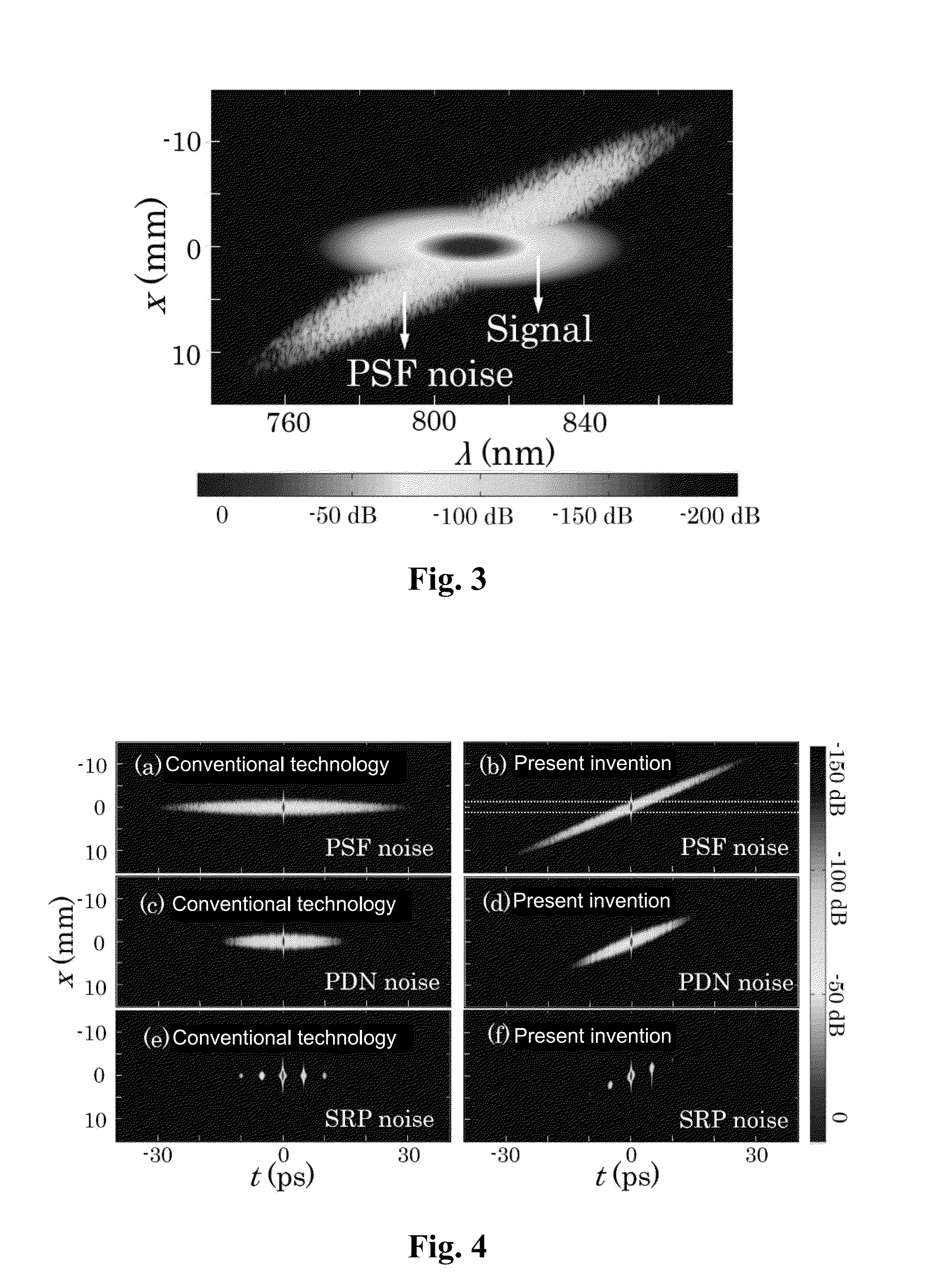
A method for filtering noises in an optical parametric chirped-pulse amplifier by a spatial-chirp-dressed seed beam is provided. The various noises that grow during amplification course, including parametric super-fluorescence, pump distortion-induced noise and surface-reflection-initiated pre-pulses, will not have the spatial and temporal chirp. After dechirping amplified signal with a compressor, a main pulse having its spatial and temporal chirp removed completely is produced, while the noises acquire an additional spatiotemporal coupling, making themselves highly distinguishable from signal in space, and hence supporting noise filtering effectively and expediently in spatial domain that would not be possible otherwise. The method has capabilities of an order of magnitude reduction in noise energy and several orders of magnitude enhancement in temporal contrast.

Description

CROSS REFERENCE OF RELATED APPLICATION[0001]This Application claims priority under 35 U.S.C. 119(a-d) to CN 201410135997.1, filed Apr. 4, 2014.BACKGROUND OF THE PRESENT INVENTION[0002]1. Field of Invention[0003]The present invention relates to a technical field of ultra-short laser amplification, and more particularly to a method for noise filtering in an optical parametric chirped-pulse amplifier and a device therefor.[0004]2. Description of Related Arts[0005]The seed beam in a conventional optical parametric chirped-pulse amplifier (OPCPA) is only temporally chirped. During the parametric amplification, the seed generally suffer from three kinds of noises: parametric super-fluorescence (PSF), pump distortion-induced noise (PDN) and surface-reflection-initiated pre-pulses (SRP). These noises then transform into broad pedestals or isolated side-pulses located around the intense main pulse after the amplified signal is compressed, which limit the temporal contrast of the amplified ul...

Claims


Application Information

Patent Timeline
IPC IPC(8): H01S3/10
CPCH01S3/10023H01S3/10084H01S3/0057G02F2001/392G02F2201/30G02F2203/26G02F1/39G02F1/392
Inventor QIAN, LIEJIAWANG, JINGYUAN, PENGMA, JINGUIWANG, YONGZHIXIE, GUOQIANG
Owner SHANGHAI JIAO TONG UNIV
Learn More