
Linear module

a technology of linear modules and tube elements, applied in the field of linear modules, can solve the problems of affecting inevitably generating bending moments on the tube elements, and hindering the telescoping engagement of the two tube elements. , to achieve the effect of reducing the bending moments

Inactive Publication Date: 2011-10-25
ROBERT BOSCH GMBH
View PDF13 Cites 11 Cited by
  • Summary
  • Abstract
  • Description
  • Claims
  • Application Information

AI Technical Summary

Benefits of technology

[0004]The object of the present invention, by contrast, is to produce a linear module in a way that reduces the bending moments acting on the tube element connected to the table part.
[0005]This object is attained according to the invention by a linear module of the type mentioned at the beginning in which the tube element connected to the table part is connected to the table part by means of a bridge piece over at least a portion of its length while the tube element connected to the baseplate unit has at least one slot for accommodating the at least one bridge piece. By virtue of the bridge piece provided according to the present invention, the tube element is not attached just at its one end, as is the case in the prior art, but instead has a stable connection to the table part over a portion of its length. The bridge piece can therefore very effectively isolate the tube element from bending moments.
[0006]Also as a result of this increased stability in relation to bending moments, the two tube elements can even be guided on each other since bending moments exerted on the tube element connected to the table part cannot, as in the prior art, lead to an increase in friction and therefore a blocking of the telescoping movement. This close guidance on each other is better able to protect the interior of the telescoping tube arrangement from the penetration of dirt without the provision of additional sealing measures. In this embodiment, it can be useful to provide a slide bushing made of plastic between the metal tubes so as to avoid unnecessary wear due to the unfavorable sliding pair of aluminum on aluminum.
[0008]According to a modification of the invention, the length of the at least one slot is dimensioned so that it is still covered by the table part even in the telescopically extended state. This, too, has advantages with regard to the penetration of dirt, but also has advantages with regard to the visual appearance of the overall apparatus.
[0011]In this case, or even if no end plate is provided on the end surface of the table part oriented away from the drive unit, in order to be able to prevent the penetration of dirt into the interior of the telescoping tube arrangement in an easy-to-manufacture way, according to another embodiment, the tube element connected to the table part, at its end oriented away from the drive unit, is closed by means of a closing element, for example a stopper preferably made of plastic. In this way, the telescoping arrangement can also be filled with lubricant, for example grease, so that it is possible to assure a durable, maintenance-free lubrication of the spindle.
[0013]If the tube element connected to the table part is embodied as separate from it and is screw-connected to it, then this permits a particularly easy manufacture of the linear module. Basically, however, it is also conceivable for the tube element connected to the table part to be of one piece with the table part, which offers particular advantages with regard to stability and is therefore accompanied by a reduction of the transmission of bending moments to the tube element. Since this feature taken by itself is also not known from the prior art, separate protection is sought for it.

Problems solved by technology

This has the disadvantage that the tube element connected to the table part, at least in the telescopically extended state, must support its own weight over a relatively long length before it telescopically engages with the tube element connected to the baseplate unit.
A more serious disadvantage, however, is that any external force to which the end plate is subjected during operation of the linear module inevitably generates bending moments on the tube element connected to the table part.
But the resulting deformations increase the friction, thus hindering the telescoping engagement of the two tube elements, when not causing a tilting of the two tubes.

Method used


Image

  • Linear module
  • Linear module
  • Linear module

Examples


Embodiment Construction

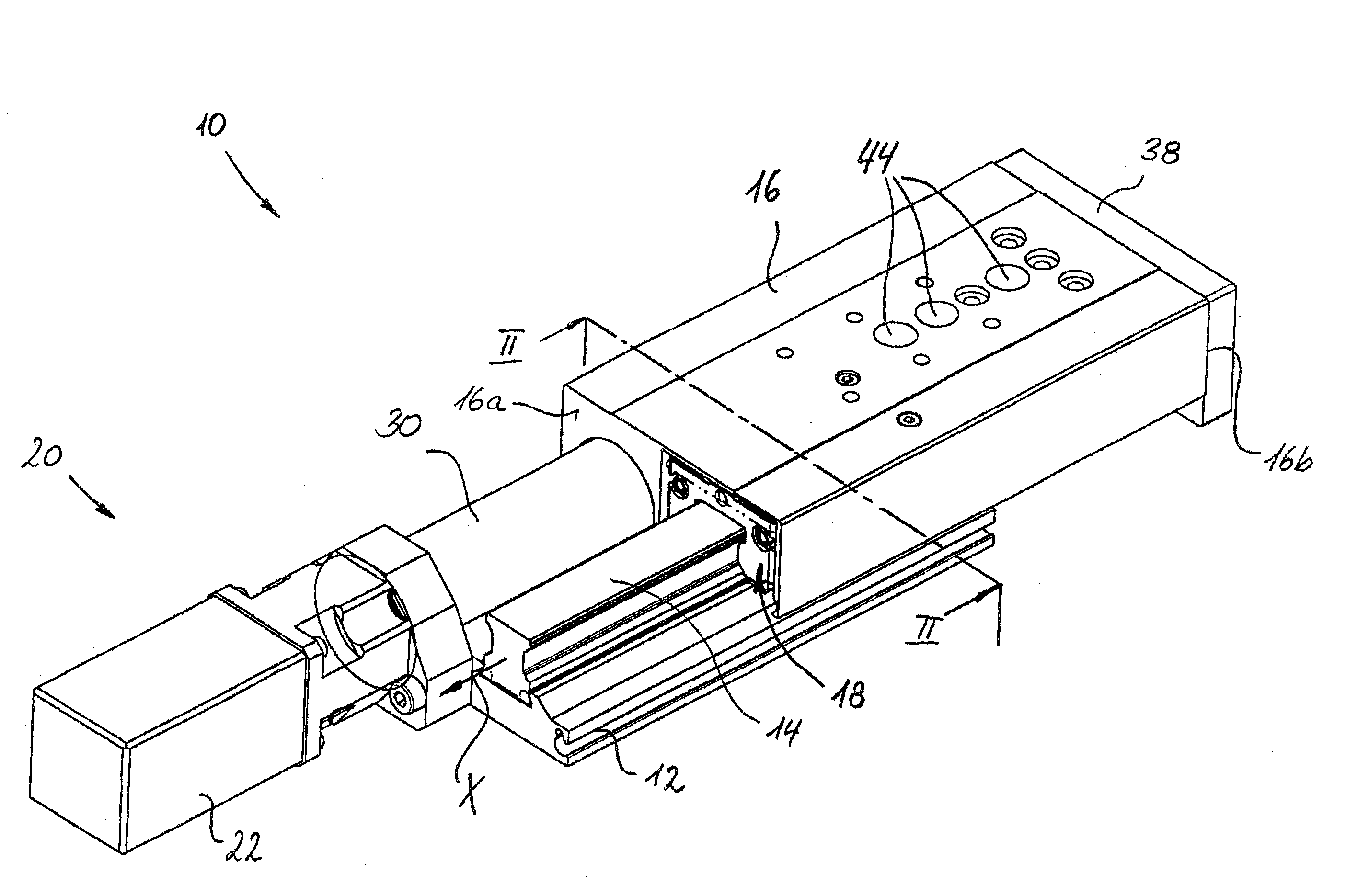
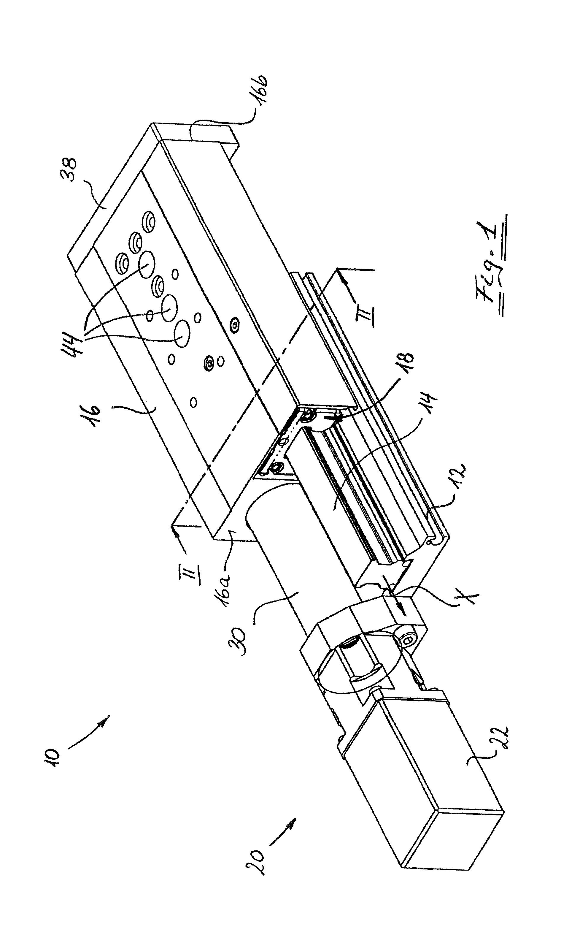
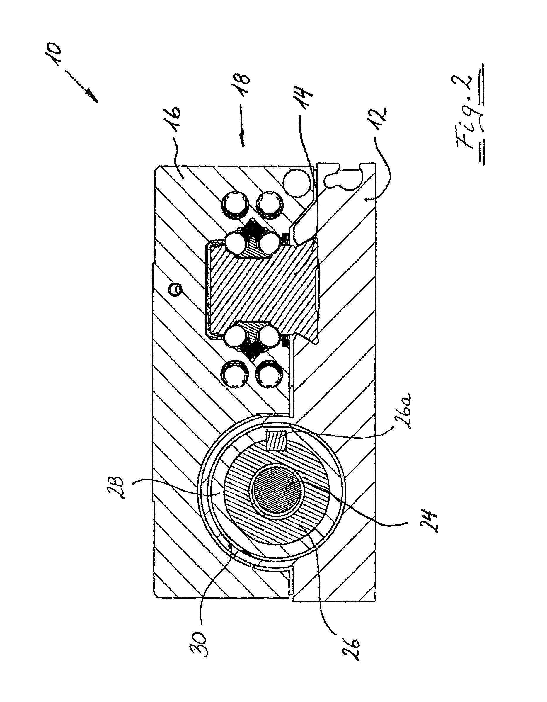
[0020]In FIGS. 1 and 2, a linear module according to the invention is labeled as a whole with the reference numeral 10. It includes a rail 14 that is mounted on a baseplate 12 and extends in a longitudinal direction X. It also includes a table part 16, which a linear guide device 18 guides so that it is able to slide on the rail 14 in its longitudinal direction X. In order to drive the table part 16 in relation to the rail 14, a spindle drive 20 is provided, with a spindle 24 that is driven by a motor 22 and engages with the threads of a nut 26.

[0021]As particularly shown in FIG. 2, the spindle 24 and nut 26 of the spindle drive 20 are encompassed by an inner tube element 28 and an outer tube element 30, which engage each other in telescoping fashion. An element 26a fastens the nut 26 in both rotatory and translatory fashion inside the inner tube element 28. FIG. 2 also shows that the outer tube element 30 is of one piece with the baseplate unit 12, while the inner tube element 28 i...


PUM

PropertyMeasurementUnit
lengthaaaaaaaaaa
weightaaaaaaaaaa
frictionaaaaaaaaaa

Abstract

A linear module includes a baseplate unit, a table part, a spindle drive device, and a telescoping tube arrangement that encompasses the spindle and that has two tube elements that engage with each other in telescoping fashion in a movement direction, namely a tube element connected to the baseplate unit and a tube element connected to the table part. The tube element connected to the table part is connected to the table part over a portion of its length by at least one bridge piece and the tube element connected to the baseplate unit has at least one slot embodied to accommodate the at least one bridge piece.

Description

CROSS-REFERENCE TO A RELATED APPLICATION[0001]The invention described and claimed hereinbelow is also described in German Patent Application DE 10 2007 006 249. 6 filed on Feb. 8, 2007. This German Patent Application, whose subject matter is incorporated here by reference, provides the basis for a claim of priority of invention under 35 U.S.C. 119(a)-(d).BACKGROUND OF THE INVENTION[0002]The invention relates to a linear module having a baseplate unit, a table part, a spindle drive device equipped with a spindle that is connected in a force-transmitting fashion to a drive unit mounted on the baseplate unit and with a nut that is connected to the table part and engages with the threads of the spindle, and a telescoping tube arrangement that encompasses the spindle and has two tube elements that engage with each other in telescoping fashion in a movement direction, namely a tube element connected to the baseplate unit and a tube element connected to the table part.[0003]A linear module...

Claims


Application Information

Patent Timeline
Patent Type & Authority Patents(United States)
IPC IPC(8): F16H3/06F16H27/02F16H29/02F16H29/20
CPCB23Q5/40B23Q11/0825F16C29/00F16C29/0602F16C29/004F16C2322/39Y10T74/18576F16H2025/204F16C29/0645Y10T74/18656Y10T74/18672F16H25/20
Inventor PFISTER, STEFFEN
Owner ROBERT BOSCH GMBH
Learn More