
Spinal fixation support device and methods of using

a technology of fixation support and spine, which is applied in the field of orthopaedic devices, can solve the problems of high instrumentation failure rate, instrumentation failure, implant failure, etc., and achieve the effects of reducing instrumentation failure, increasing the effectiveness of spinal fixation instruments, and reducing bending moments

Active Publication Date: 2006-06-08
MAYO FOUND FOR MEDICAL EDUCATION & RES
View PDF22 Cites 0 Cited by
  • Summary
  • Abstract
  • Description
  • Claims
  • Application Information

AI Technical Summary

Benefits of technology

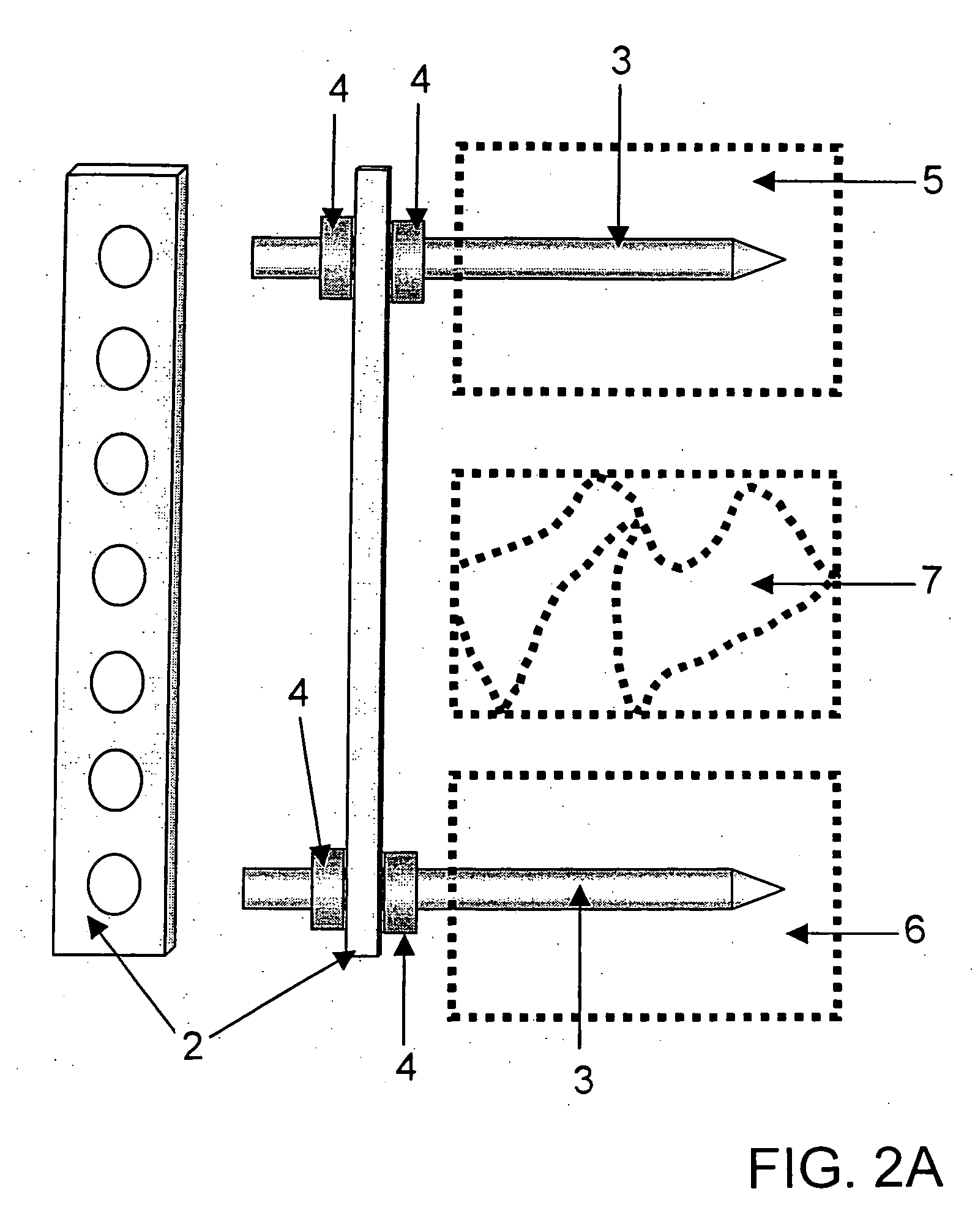
[0003] The invention provides a spinal fixation support device and methods of using such a device in conjunction with spinal fixation instrumentation. In addition, the invention provides for a spinal fixation system that includes a spinal fixation support device of the invention and spinal fixation instrumentation. The spinal fixation support device reduces the bending moment applied to spinal fixation instrumentation, thus reducing instrumentation failure and increasing the effectiveness of spinal fixation instrumentation.

Problems solved by technology

Although fusion rates have improved with the use of SSPI, a high rate of instrumentation failure is still a significant problem.
In most cases, instrumentation failure occurs due to either implant failure or bone failure.
Implant failure occurs when a screw bends or breaks.
Bone failure occurs when the bone is weak and / or osteoporotic, resulting in loosening, toggling, or pullout of the screws.
In cases of failure, a second operation is necessary, leading to increased risk of complications and higher medical costs.
Anterior loading to a posterior construct is a major reason for failure of SSPI.
However, a second operation has to be performed from an anterior approach, increasing risk and medical costs.

Method used


Image

  • Spinal fixation support device and methods of using
  • Spinal fixation support device and methods of using
  • Spinal fixation support device and methods of using

Examples


example 1

Mechanical Testing of the Pillar System Using a Synthetic Resin Spine

[0040] Mechanical testing of the pillar system was performed using synthetic resin vertebrae (Acetal; Delrin, Precision Punch & Plastics Co., Minnetonka, Minn.). Dick short-segment pedicle instrumentation (Internal skeleton fixation system ISFS; Sulzer Ltd CH-8401, Winterthur, Switzerland) was used as the spinal fixation instrumentation. The specimen was mounted on a servohydraulic machine (MTS, Minneapolis, Minn.). An axial load of 10 N / m torque was applied to the top of the vertebral body (195 Newton load with a 0.052 meter moment arm) (FIG. 5). This axial load to the vertebral body is commonly used for mechanical testing (see, for example, Dooris et al., 2001, Spine, 26:E122-9, and references therein). The testing was first performed without a pillar system. After pillars were installed, the test was repeated. The load and displacement of the vertebrae were recorded at 20 Hz. FIG. 6 shows the results from such ...

example 2

Mechanical Testing of the Pillar System Using a Human Cadaver Spine

[0041] A human cadaver spine from T12 to L2 was harvested for the mechanical test. The anterior three-fourths of the L1 vertebral body was resected to simulate a severe non-load-bearing situation. Compression of the harvested spine was performed by hand until the T12 touched the L2 anteriorly to create an unstable spine model.

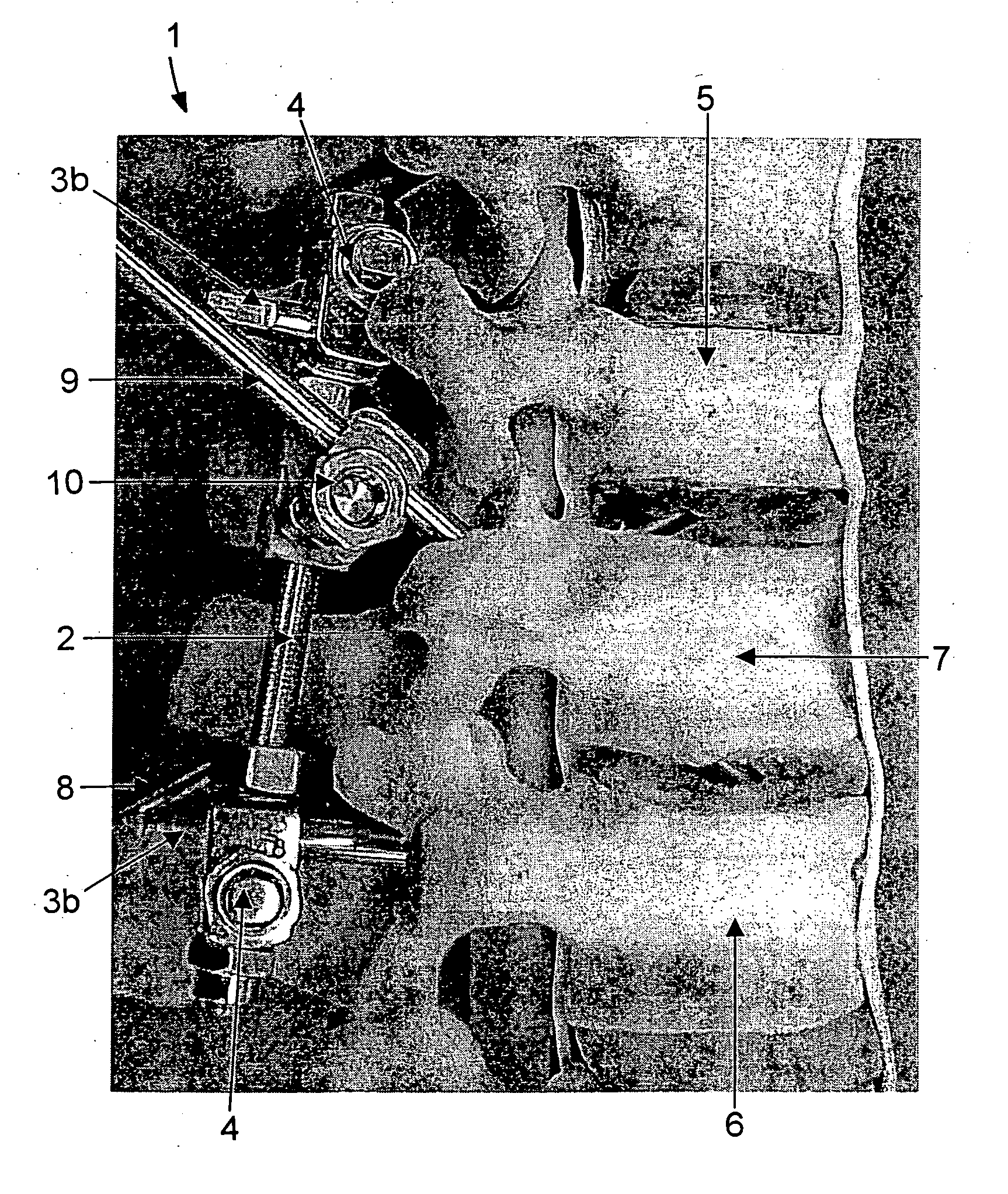
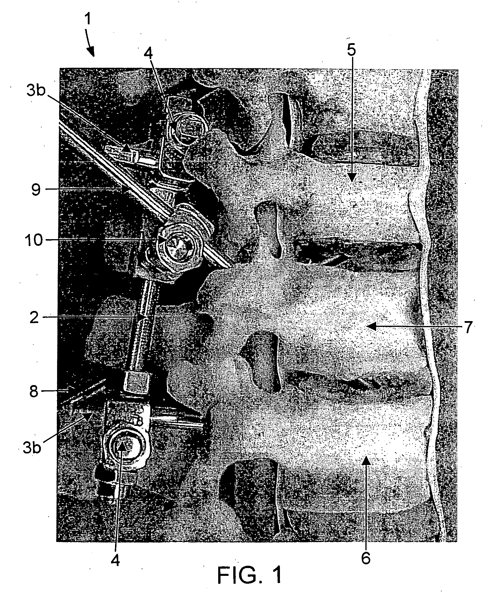
[0042] The two pedicles in the L1-fractured vertebra were prepared for pillar insertion as described herein. Following preparation of the holes for pillar insertion, Dick spinal fixation instrumentation using 5 mm pedicle screws was installed between T12 and L1 using a standard surgical procedure as would be performed by an orthopedic surgeon. The bottom of the L2 vertebral body was embedded in bone cement and the specimen was mounted in the servohydraulic machine for mechanical testing (FIG. 7A). An axial load of 7.5, 10, or 15 N / m torque was applied anteriorly to the top of the vertebral bod...


PUM


Abstract

The invention provides for a spinal fixation support device to be used in conjunction with spinal fixation instrumentation. The invention further provides for methods of using the spinal fixation support device. In addition, the invention provides for a spinal fixation system that includes a spinal fixation support device of the invention and can further include spinal fixation instrumentation.

Description

TECHNICAL FIELD [0001] This invention relates generally to an orthopedic device, and more specifically, to a spinal fixation support device and methods of using such a device. BACKGROUND [0002] During the last 30 years, the development of instrumentation for internal spinal fixation has evolved rapidly to provide a variety of surgical options. In order to preserve motion segments, avoid long fusion, and provide a stable construct, posterior short-segment pedicle instrumentation (SSPI) has been widely used in unstable vertebral fracture for short segment fixation. Although fusion rates have improved with the use of SSPI, a high rate of instrumentation failure is still a significant problem. In most cases, instrumentation failure occurs due to either implant failure or bone failure. Implant failure occurs when a screw bends or breaks. Bone failure occurs when the bone is weak and / or osteoporotic, resulting in loosening, toggling, or pullout of the screws. In cases of failure, a second...

Claims


Application Information

Patent Timeline
Patent Type & Authority Applications(United States)
IPC IPC(8): A61F2/30A61B17/70
CPCA61B17/70A61B17/7007A61B17/701A61B17/7058
Inventor ZHAO, CHUNFENGCURRIER, BRADFORD L.SCHULTZ, FREDRICK M.AN, KAI-NAN
Owner MAYO FOUND FOR MEDICAL EDUCATION & RES
Learn More