
Vehicle transmission

a technology for transmission and vehicle, applied in the direction of gearing control, gearing element, belt/chain/gearing, etc., can solve the problems of increasing design manhours, increasing enlarge the transmission, so as to prevent an increase in the diameter of the shift drum, reduce the number of shift positions set on the shift drum, and eliminate the significant change in the shape of the lead groove

Active Publication Date: 2011-10-25
HONDA MOTOR CO LTD
View PDF6 Cites 11 Cited by
  • Summary
  • Abstract
  • Description
  • Claims
  • Application Information

AI Technical Summary

Benefits of technology

[0007]The present invention has been made in view of the foregoing and it is an object of the present invention to provide a vehicle transmission that can prevent an increase in the diameter of the shift drum and eliminate the significant change of the shape of a lead groove even if the number of shift positions set on the shift drum is increased.
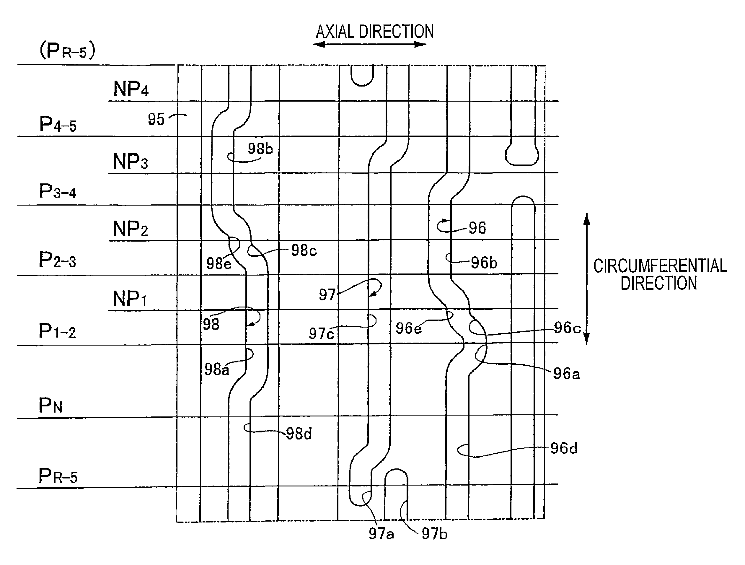
[0019]According to the embodiment of the present invention, at least one particular lead groove among the lead grooves formed on the shift drum continuously extends beyond one circle of the shift drum and both ends of the second lead groove are arranged so as to be out of alignment with each other in the axial direction of the shift drum, and the common shift position adapted to establish gear trains with two shift stages different from each other is set on the shift drum at one position corresponding to both the ends of the particular lead groove. Thus, the number of the shift positions set on the shift drum can be increased while the enlargement of the transmission resulting from the increased diameter of the shift drum is avoided and an increase in design manhours is avoided by eliminating the significant modification of the shape of the lead groove.
[0020]According to the embodiment of the present invention, the particular lead groove is formed to be stepwise offset to one side of the shift drum in the axial direction thereof as it goes from the one end thereof to the other end. Thus, while both the ends of the particular lead groove are arranged to be out of alignment with each other in the axial direction of the shift drum, the axial enlargement of the shift drum can be prevented without an influence on the operation of the shift fork.
[0022]According to the embodiment of the present invention, since the engine start approval / disapproval process is performed at the time of starting the engine, the shift position can reliably be confirmed even if the shift drum is at the common shift position.

Problems solved by technology

However, in the vehicle transmission configured as disclosed in Japanese Utility Model Publication No. 62-8683, to increase the shift positions set on the shift drum, the increased diameter of the shift drum enlarges the transmission and the significant change of the shape of a lead groove increases design manhours.

Method used


Image

  • Vehicle transmission
  • Vehicle transmission
  • Vehicle transmission

Examples


Embodiment Construction

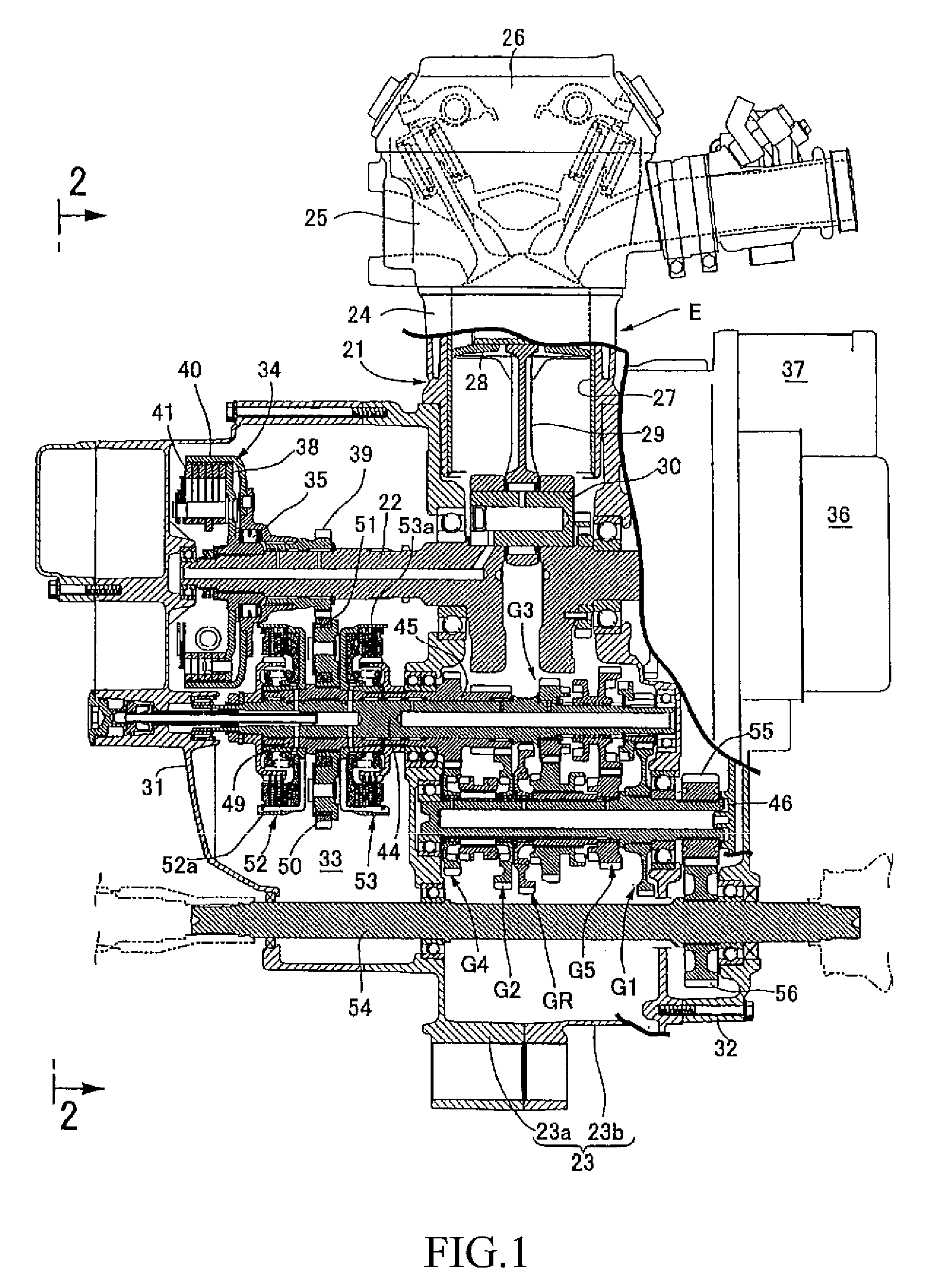
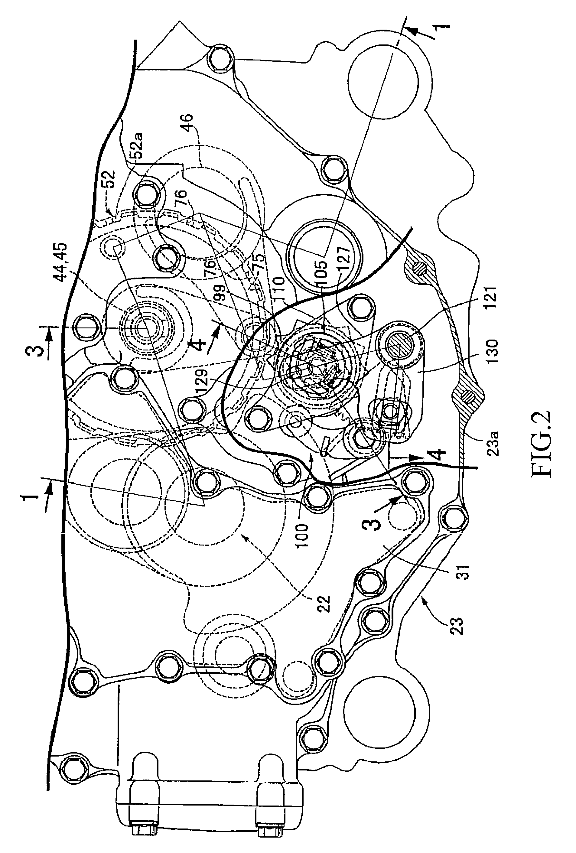
[0044]Referring first to FIG. 1, an engine main body 21 of an engine E mounted on e.g. an all terrain vehicle (ATV) includes a crankcase 23, a cylinder block 24, a cylinder head 25, and a head cover 26. The crankcase 23 rotatably journals a crankshaft 22 having an axial line extending vehicle-widthwise (a direction parallel to the sheet surface of FIG. 1). The cylinder block 24 is joined to the upper portion of the crankcase 23. The cylinder head 25 is joined to the upper portion of the cylinder block 24. The head cover 26 is joined to the upper portion of the cylinder head 25. A piston 28 slidably fitted into the cylinder bore 27 of the cylinder block 24 is connected to the crankshaft 22 via a connecting rod 29 and via a connecting pin 30.

[0045]The crankcase 23 is composed of a pair of case half bodies 23a, 23b joined together at a plane perpendicular to the rotational axis of the crankshaft 22. First and second crankcase covers 31, 32 are respectively fastened to both sides of the...


PUM


Abstract

An outer circumference of a shift drum of a vehicle transmission is provided with at least one particular lead groove among multiple lead grooves which continuously extends beyond one circle of the shift drum. Two ends of the particular lead groove are arranged so as to be out of alignment with each other in the axial direction of the shift drum. A common shift position adapted to establish gear trains with two shift stages different from each other is set at one position corresponding to the two ends of the particular lead groove along the circumferential direction of the shift drum. The resulting configuration prevents an increase in the diameter of a shift drum and eliminates the significant change of the shape of a lead groove, even as the number of shift positions set on the shift drum is increased.

Description

CROSS-REFERENCE TO RELATED APPLICATION[0001]The present application claims priority under 35 U.S.C. §119 to Japanese Patent Application No. 2007-083263, filed Mar. 28, 2007, the entire contents of which are hereby incorporated by reference.BACKGROUND OF THE INVENTION[0002]1. Field of the Invention[0003]The present invention relates to a vehicle transmission including gear trains with a plurality of shift stages which can selectively be established; a shift drum provided in the outer with at least one circumferentially extending lead groove; drive means for rotatably driving the shift drum; a shift fork which has a shift pin slidably engaged with the lead groove and switches the established states of the gear trains with gear stages according to the operation resulting from the turning of the shift drum.[0004]2. Description of Background Art[0005]Such a vehicle transmission is known from e.g. patent document 1, in which, to alternatively establish gear trains with a plurality of shif...

Claims


Application Information

Patent Timeline
Patent Type & Authority Patents(United States)
IPC IPC(8): F16H63/18
CPCF16H63/18F16H61/32Y10T74/19251Y10T74/19279
Inventor MIZUNO, KINYASUMI, HIROMITAKAHASHI, MASAKOKOBAYASHI, MASAKIKITTAKA, EIJI
Owner HONDA MOTOR CO LTD
Learn More