Articulation device for an awning elbow joint

a technology for articulating devices and elbows, which is applied in the direction of sunshades, shafts and bearings, mechanical equipment, etc., can solve the problems of difficult and economically expensive machining of elbow parts, friction bushings that cannot withstand limited axial and radial stresses, and achieves cost-effectiveness. , the effect of more cost-effectiv

Inactive Publication Date: 2011-10-25
LLAZA
View PDF8 Cites 21 Cited by
  • Summary
  • Abstract
  • Description
  • Claims
  • Application Information

AI Technical Summary

Benefits of technology

[0009]An articulation device with two roll bearings at the ends of the axial hole of the core installed according to the present invention can allow the second semi-arm to be longer than in the comparable articulated arms of the state of the art by virtue of the larger allowable axial and radial forces. Furthermore, the installation of the roll bearings according to the present invention is more cost-effective than a hypothetical installation of roll bearings with prior machining of the seats. An articulation device with two friction bushings at the ends of the axial hole of the core installed according to the present invention can be more cost-effective than in the comparable articulated arms of the state of the art due to the absence of machining in the seats. The possibility of an articulation device according to the present invention combining a friction bushing at one end of the axial hole of the core and a bearing at the opposite end is also provided.

Problems solved by technology

The operations for machining the elbow parts are carried out after the injection moulding and after a step of painting or lacquering the parts, and are difficult and economically expensive.
Furthermore, friction bushings withstand limited axial and radial stresses compared to roll bearings, which limits the extension that the second semi-arm may have to be supported in a cantilevered manner by the articulation configuration with respect to the end of the first semi-arm.

Method used


Image

  • Articulation device for an awning elbow joint
  • Articulation device for an awning elbow joint
  • Articulation device for an awning elbow joint

Examples


first embodiment

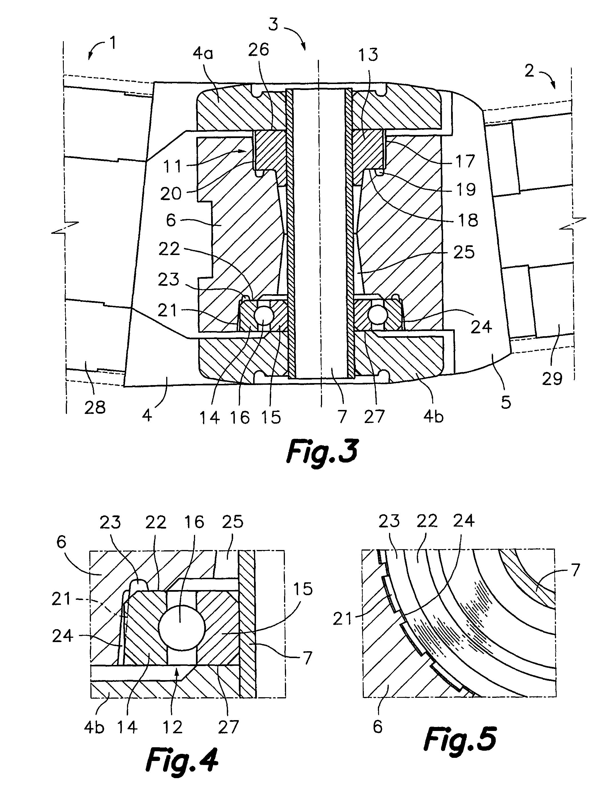
[0023]FIGS. 4 and 5 show in detail the installation of the outer annular element 14 of the roll bearing 12 in the corresponding seat of the core 6, according to the present invention. This seat comprises a conical radial support surface 21, coaxial with the shaft 7, and an axial support surface 22, perpendicular to the shaft 7. A circumferential channel 23 is formed in said axial support surface 22, in a position adjacent to said conical radial support surface 21. The mentioned outer radial rest surface of the outer annular element 14 is in the form of a continuous cylindrical surface, whereas the conical radial support surface 21 of the seat is in the form of a discontinuous conical surface due to grooves 24 formed therein. The mentioned grooves 24 extend in the directrix directions and the width of the portions of the discontinuous conical radial support surface 21 is generally less than the width of the grooves 24. The cylindrical outer radial rest surface of the annular element ...

second embodiment

[0026]In this second embodiment, the single annular element 13 of the friction bushing 11 is fixedly joined to the core 6, which forms part of the second elbow part 5. The shaft 7 provides a radial support surface adapted to slidingly support an inner radial rest surface defined by said annular element 13 of the friction bushing 11 and the corresponding branch 4a of the fork provides an axial support surface 26 adapted to make sliding contact with an axial rest surface defined by the annular element 13 of the friction bushing 11. The shaft 7 is fixedly joined to the branches 4a, 4b of the fork, which forms part of the first elbow part 4. The annular element 13 of the friction bushing 11 optionally has an extension 31 defining a conical outer surface adapted to be fitted by plugging into the conical inner surface of the axial hole 25 of the core 6. Furthermore, to prevent a relative rotation between the annular element 13 of the friction bushing 11 and the core 6, the annular element...


PUM


Abstract

An articulation device applicable to an awning arm elbow includes a fork and a core which are joined to respective first and second semi-arms and are connected to one another by an articulation shaft. The core has an anchor in an outer surface for hooking an enlarged end of a flexible, elastically loaded tie rod which is accommodated in the first semi-arm. A seat with conical radial and axial support surfaces is formed in the core, and a circumferential channel is formed in the axial support surface. A bearing unit includes an annular element with a cylindrical outer radial rest surface to be fitted, by pressurized insertion with interference, into the conical radial support surface of the seat, and an axial rest surface to rest against the axial support surface of the seat.

Description

[0001]This application is a U.S. National Phase Application of PCT International Application No. PCT / ES2007 / 000540, filed Sep. 24, 2007.TECHNICAL FIELD[0002]The present invention relates to an articulation device applicable to an awning arm elbow, said awning arm being of the type formed by two semi-arms articulated in said elbow, where the free end of the first semi-arm is provided with a configuration for articulated attachment to a fixed support adjacent to a winding tube for the canvas of the awning and the free end of the arm is provided with a configuration for articulated attachment to a load bar fixed to a front edge of the canvas, and where inside the first semi-arm there is arranged an elastic traction member connected to a flexible tie rod element having an end anchored in the mentioned articulation device for the elbow.BACKGROUND OF THE INVENTION[0003]Patent ES-A-2191843 discloses an articulated arm for an awning of the type described above, formed by a first semi-arm an...

Claims


Application Information

Patent Timeline
Patent Type & Authority Patents(United States)
IPC IPC(8): E04F10/06
CPCE04F10/0622E04F10/0651F16C11/045
Inventor LLAGOSTERA FORNS, JOAN
Owner LLAZA
Why Eureka
Try Eureka