Modular light reflectors and assemblies for luminaire

a module-type light and reflector technology, applied in the field of luminaires, can solve the problems of high power equipment and energy consumption, uncontrolled light waste, and interference with the preservation and protection of the nighttime environment, and achieve the effects of reducing the number of different parts, reducing the size of parts maintained in inventory, and lowering the cost of inventory and manufacturing

Inactive Publication Date: 2011-10-25
LSI INDS
View PDF61 Cites 64 Cited by
  • Summary
  • Abstract
  • Description
  • Claims
  • Application Information

AI Technical Summary

Benefits of technology

[0009]The reflector modules of the present disclosure permit the manufacture of different reflector assemblies from reflector modules of the same configuration by orienting one or more of the reflector modules differently. The reflector assemblies of the present disclosure also permits the manufacture of reflector assemblies comprising reflector modules of different configurations. The reflector of the present disclosure thus provides multiple reflector assembly configurations with relatively fewer configurations of reflector modules. The disclosed reflector assemblies thereby lower the number of different parts required to be manufactured or maintained in inventory and decreases the size of parts maintained in inventory thereby lowering costs of inventory and manufacturing while increasing manufacturing flexibility.

Problems solved by technology

Uncontrolled light can be wasted in lighting areas around the target area to be lighted, and contributes to unwanted “night lighting” which can interfere with the preservation and protection of the nighttime environment and our heritage of dark skies at night.
Uncontrolled light also necessitates generation of greater amounts of light to meet the lighting requirements in the target area requiring higher power equipment and energy consumption to provide the target area with the desired amount of light.

Method used


Image

  • Modular light reflectors and assemblies for luminaire
  • Modular light reflectors and assemblies for luminaire
  • Modular light reflectors and assemblies for luminaire

Examples


Embodiment Construction

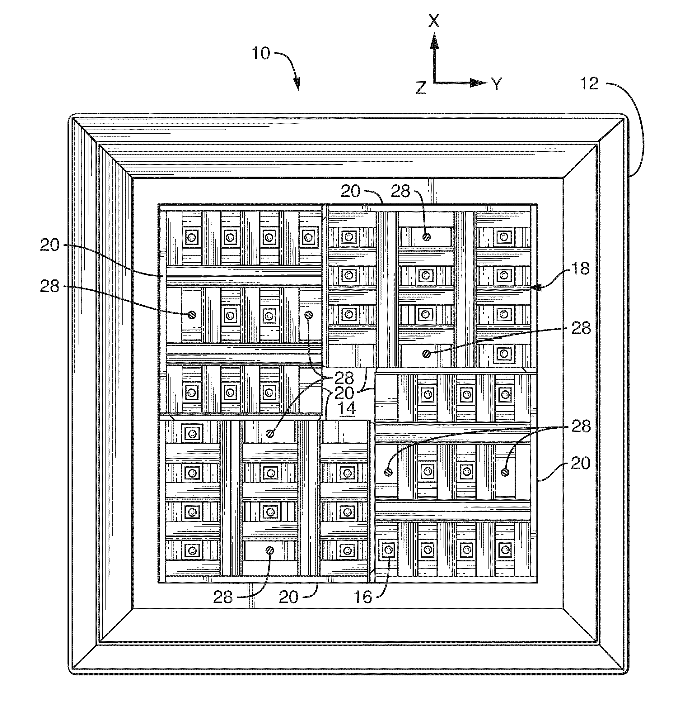
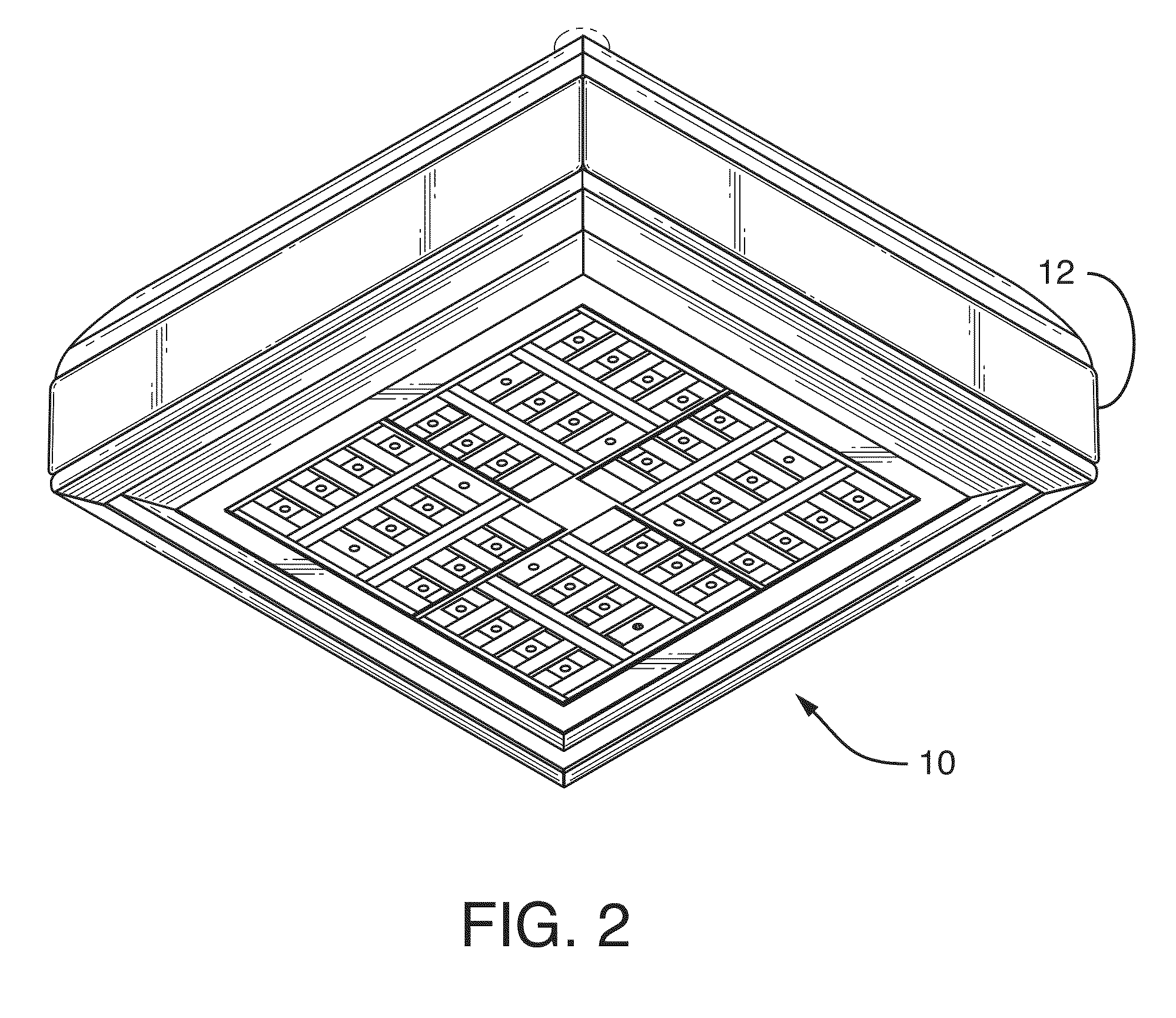
[0031]FIG. 3 depicts a lighting apparatus 10 comprising a housing 12 of the type disclosed in copending U.S. patent application Ser. No. 12 / 236,243 filed Sep. 23, 2008, the entirety of which is incorporated herein by reference. Lighting apparatus 10 has a base 14 having a plurality of light sources 16. The lighting sources 16 are depicted as LEDs, but may be any other light source and the term “light source” as used herein generically refers to LEDs or any other light sources known to date or hereinafter created. The lighting apparatus 10 has a reflector assembly 18 comprised of reflector modules 20. The reflector assembly 18 of the lighting apparatus 10 is depicted as having four reflector modules 20. However, a reflector assembly could be comprised of any number of reflector modules. It is contemplated that any size reflector assembly could be created by piecing together a sufficient number and / or size of reflector modules. Similarly, despite the fact that the reflector assembly 1...


PUM


Abstract

A reflector assembly for a lighting apparatus, the reflector assembly comprising two or more reflector modules configured for associating with one or more light sources, each reflector module comprising one or more reflectors for being located adjacent to a light source when the reflector module is associated with the one or more light sources, the one or more reflectors configured to reflect light from the adjacent light source. The reflector modules may further comprising a cover plate defining a plurality of light source apertures for allowing a light source to protrude through the cover plate, at least a first of the one or more light source apertures disposed adjacent to an overhead reflector and at least a second of the one or more light source apertures disposed adjacent to a lateral reflector. The reflector assembly can comprising any number of reflector modules and the reflector modules can be arranged in different configurations to create different light distributions with the same reflector modules.

Description

FIELD OF THE DISCLOSURE[0001]The present disclosure relates generally to a luminaire and, more particularly, to a luminaire for lighting an area such as a parking lot, parking garage, roadway or the like and, even more particularly, to a reflector assembly having a plurality of modular reflectors for directing light from one or more light sources. The disclosure finds particularly useful application when the luminaire employs multiple light sources including, in one embodiment, one or more light emitting diodes (LEDs).BACKGROUND OF THE DISCLOSURE[0002]Uncontrolled light can be wasted in lighting areas around the target area to be lighted, and contributes to unwanted “night lighting” which can interfere with the preservation and protection of the nighttime environment and our heritage of dark skies at night. Uncontrolled light also necessitates generation of greater amounts of light to meet the lighting requirements in the target area requiring higher power equipment and energy consu...

Claims


Application Information

Patent Timeline
Patent Type & Authority Patents(United States)
IPC IPC(8): F21V1/00
CPCF21V7/0083F21Y2101/02F21Y2105/001F21Y2105/10F21Y2115/10
Inventor BOYER, JOHN D.VANDEN EYNDEN, JAMES G.AKERS, LARRY A.
Owner LSI INDS
Why Eureka
Try Eureka