Method for determining an imaging rule and method for generating a 3D reconstruction

a 3d reconstruction and imaging rule technology, applied in the direction of tomography, material analysis using wave/particle radiation, instruments, etc., can solve the problems of calibration phantom, inability to determine imaging rules at any position of imaged components as required, and inability to determine imaging rules

Active Publication Date: 2011-10-25
SIEMENS HEALTHCARE GMBH
View PDF13 Cites 38 Cited by
  • Summary
  • Abstract
  • Description
  • Claims
  • Application Information

AI Technical Summary

Problems solved by technology

If the calibration phantom is placed on the patient table, this means that the determination of an imaging rule at any positions of the imaged components as required is not possible.
At some positions, the amount of the calibration phantom that can be recorded is so small that a determination of an imaging rule is not possible.
If the calibration phantom from the article by Strobel et al. is used, this would make the determination of the imaging rule impossible on the basis of a single X-ray image alone.

Method used


Image

  • Method for determining an imaging rule and method for generating a 3D reconstruction
  • Method for determining an imaging rule and method for generating a 3D reconstruction
  • Method for determining an imaging rule and method for generating a 3D reconstruction

Examples


Embodiment Construction

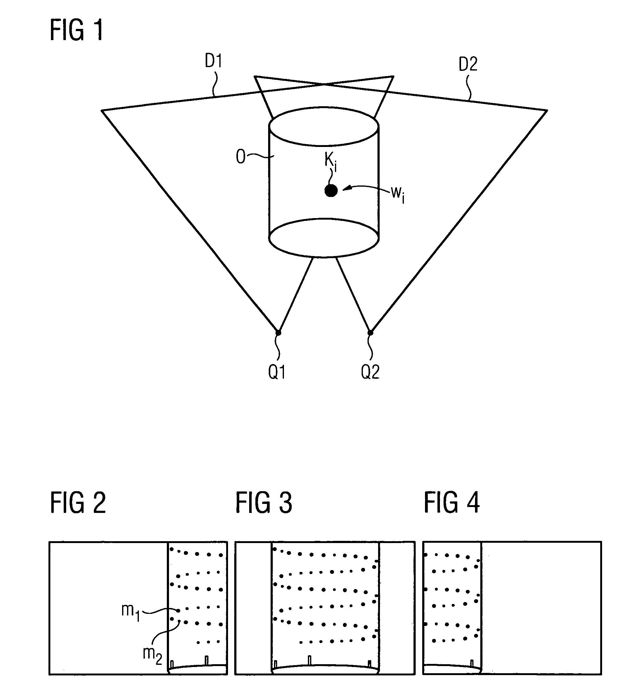
[0035]DE 10 2006 041033.5 describes how two different X-ray images are taken, which together cover the body, for the generation of a 3D reconstruction of a particularly large body, which cannot be imaged by a single projection. The X-ray detector is tilted between the taking of the two X-ray images. Basically, it is assumed that the X-ray radiation source remains at the same location, but this can also move in an actual radiographic imaging system. DE 10 2007 026 115.4 deals with the latter case and this is also shown in FIG. 1. In this case, an X-ray radiation sources Q1 radiates X-ray radiation on to an X-ray detector D1 and in a second position the X-ray source Q1 has moved to a point different from the X-ray source Q2, and the detector D1 has moved in a different plane and is therefore designated as D2. The method according to DE 10 2007 026 115.4 requires an imaging rule for the imaging of points in the 3D space on points in a 2D X-ray image, i.e. on the detectors D1 and D2. No...


PUM


Abstract

It is possible that at a predetermined position of the imaging components of a radiographic imaging system the object is not fully viewed. The object can be a calibration phantom, which means that it is not possible to directly determine an imaging rule with the aid of the calibration phantom at this position of the imaging components. According to the invention, an imaging of the calibration phantom at a different position takes place and an imaging rule for this position is determined. This is then converted, provided a movement parameter is known which describes the movement from the position with the record of the calibration phantom to a different position. The imaging rule obtained in this way can be further improved, e.g. with the aid of a recording of the calibration phantom from the position in question, including if the calibration phantom is not completely imaged.

Description

CROSS REFERENCE TO RELATED APPLICATIONS[0001]This application claims priority of German application No. 10 2007 042 333.2 filed Sep. 6, 2007, which is incorporated by reference herein in its entirety.FIELD OF THE INVENTION[0002]The invention relates to a method for determining an imaging rule for imaging points in the 3D space on points in a 2D X-ray image at any positions of the imaging components of a radiographic imaging system, i.e. those components with whose help the 2D X-ray image is generated. Knowledge of such a rule is necessary, especially for a method for generating a 3D reconstruction of a body located in a radiographic imaging system, with the reverse image then normally being used for the 3D reconstruction.BACKGROUND OF THE INVENTION[0003]The relevant area of expertise has long been engaged in determining imaging rules. U.S. Pat. Nos. 5,963,612 and 5,963,613 are examples of this. The imaging rule is normally determined with the aid of a “calibration phantom”. Such a c...

Claims


Application Information

Patent Timeline
Patent Type & Authority Patents(United States)
IPC IPC(8): A61B6/03
CPCG01N23/046A61B6/583G01N2223/419
Inventor VOGT, FLORIANKUNZE, HOLGERHEIGL, BENNO
Owner SIEMENS HEALTHCARE GMBH
Why Eureka
Try Eureka