Luminaire arrangement with cover layer

a technology of luminaires and covers, applied in the direction of lighting support devices, instruments, lighting and heating apparatus, etc., can solve the problems of heat dissipation, particular requirements, and drawbacks of existing led luminaires, and achieve the effects of facilitating luminaire arrangement to harmonize with the surroundings, good light efficiency, and enhanced transparency

Active Publication Date: 2011-11-01
SIGNIFY HLDG BV
View PDF11 Cites 40 Cited by
  • Summary
  • Abstract
  • Description
  • Claims
  • Application Information

AI Technical Summary

Benefits of technology

[0014]The cover layer allows for creating an adapted exterior appearance of a luminaire in the target direction, and may at the same time serve as protection of the light guide, both from physical damages but also from undesired optical contact caused by e.g. dust or other particles, and / or other objects in the environment where the luminaire is placed. Such undesired optical contact risk to impair the light guiding capabilities and result in out coupling of light at locations and in directions that are not desirable. The surface of the cover layer facing the target direction may e.g., without the risk of undesired optical contact, be provided with a texture that match the ambient environment where the luminaire is placed, e.g. a wallpaper.
[0036]Preferably, the holes are arranged in the plane of the light guide according to a staggered distribution. More preferably, the holes are arranged such that light in-coupled from a row of holes will not hit the second out-coupling facets of the next row of holes. This allows improvement of the light mixing properties of the luminaire arrangement. The light mixing in the light guide makes the luminaire arrangement robust for flux and color differences between the LEDs and also for failure of a few LEDs per m2.

Problems solved by technology

However, existing LED luminaries may suffer from a number of drawbacks.
This requirement, however, can be particular hard to meet when a plurality of small light sources are used, such as in LED based luminaries.
Another problem is heat dissipation, where temperatures at individual light sources often tend to be higher than what is desired.
Controlling and power supplying the plurality of light sources can also be hard to accomplish without negatively affecting the luminous flux.
Yet another problem is that that a luminaire should be able to present an appealing appearance.

Method used


Image

  • Luminaire arrangement with cover layer
  • Luminaire arrangement with cover layer
  • Luminaire arrangement with cover layer

Examples


first embodiment

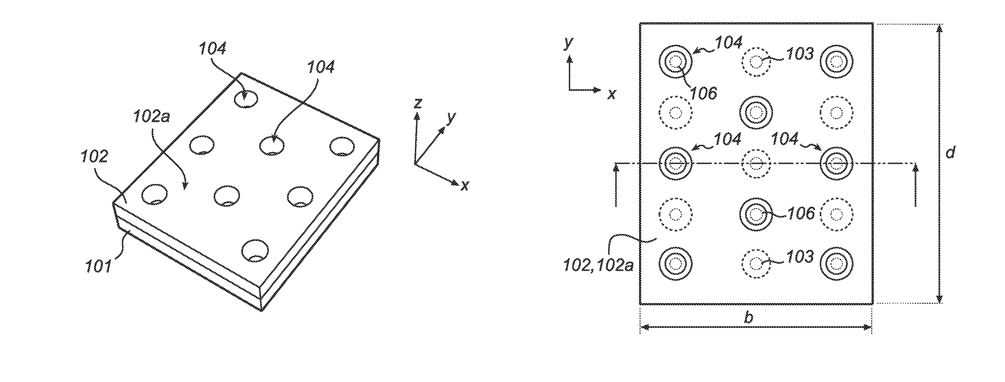
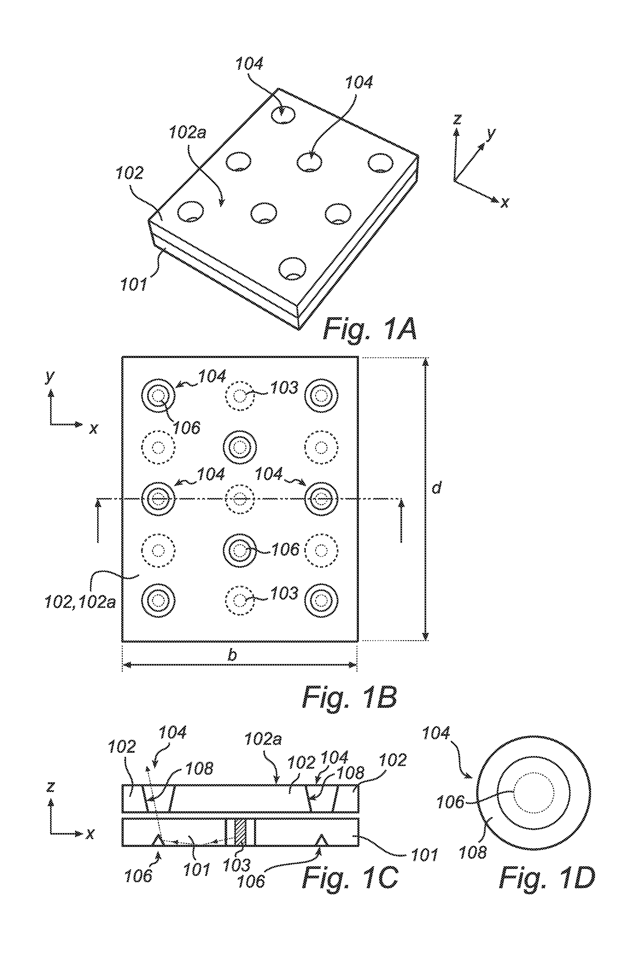
[0053]FIG. 1a is a schematic view in perspective of a luminaire arrangement with cover layer according to a A cover layer 102 is arranged in front of and attached to a light guide 101. FIG. 1b is a schematic top view of the luminaire arrangement of FIG. 1a, showing the surface 102a of the cover layer 102. Underlying out coupling means 106 and light sources 103 are outlined with dotted lines.

[0054]There are multiple light sources 103 arranged at the light guide for emitting light therein. The light is spread and mixed in the light guide and then directed out from the light guide in a target direction z by out coupling means 106 arranged at the light guide. The material of the light guide is typically PMMA or PC. The cover layer 102 is light obstructing but is provided with areas 104 that are transparent to the emitted light and arranged so that the light being directed out from the light guide via the outcoupling means pass via these areas. The cover layer has a major surface 102a t...

second embodiment

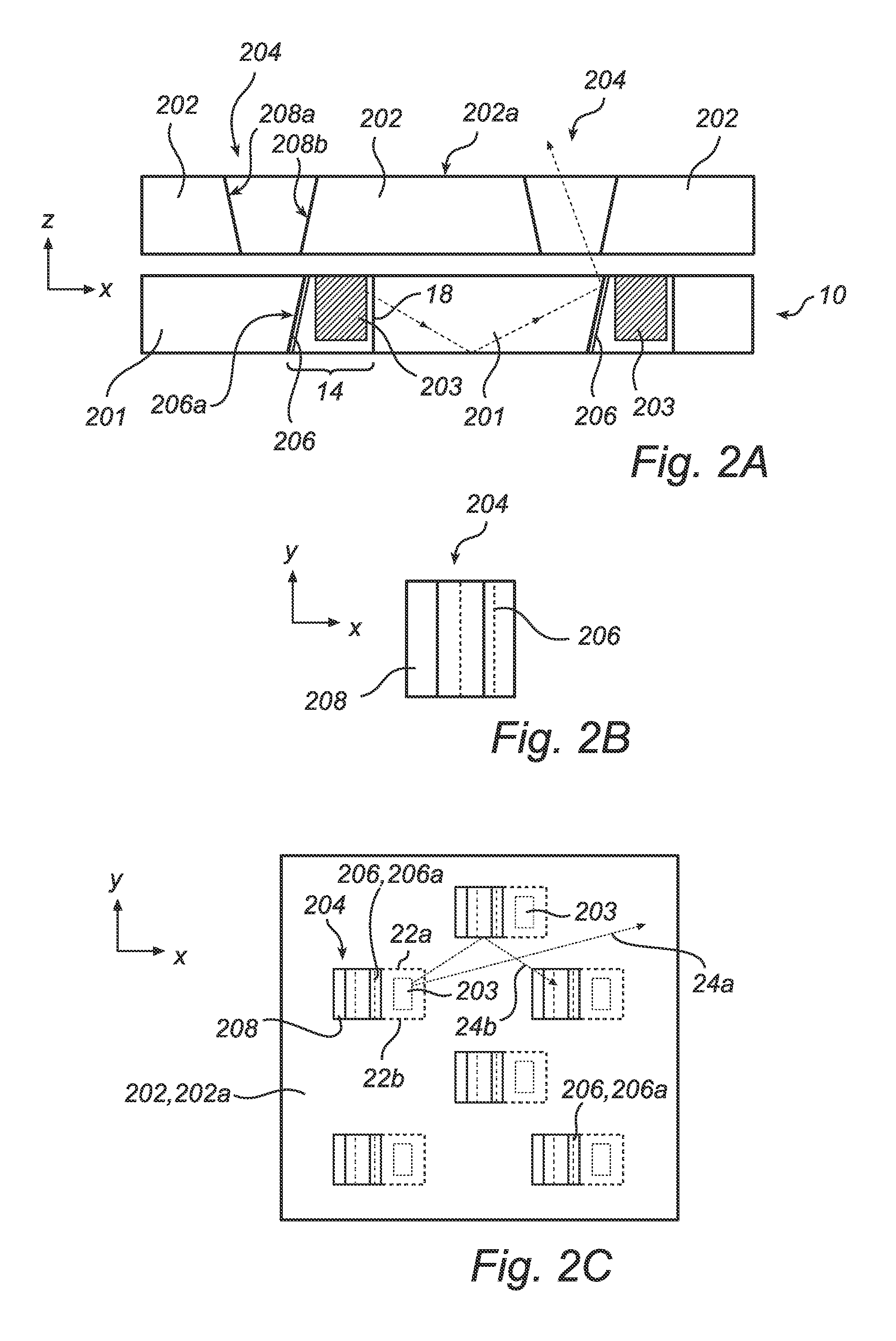
[0060]FIG. 2a is a schematic side view of a luminaire arrangement with a cover layer 202 and is showing a cross section of a light guide 201 and the cover layer 202. An exemplary light ray-trace is shown by a dotted arrow.

[0061]FIG. 2b is a schematic top view at a transparent area 204 in the cover layer 202 of the luminaire arrangement of FIG. 2a, and FIG. 2c is a top view of the luminaire arrangement of FIG. 2a. The transparent area 204 is here viewed from the target direction z and has a rectangular cross-section. The underlying out coupling means 206, in this embodiment a tilted mirror, is outlined with dotted lines.

[0062]Also in this embodiment a transparent area 204 of the cover layer comprises a funnel shape aperture. The aperture has two opposite inner surfaces 208a, 208b and is located so that light redirected by the out coupling means is allowed to pass through the aperture. Light in the light guide, which has been emitted by light sources 203, is reflected in a mirror fac...

third embodiment

[0078]FIG. 4 is a schematic side view of a luminaire arrangement with a cover layer where a transparent area 404 in a cover layer 402 is adapted to the degree of collimation (alternatively non-collimation) of light from the light guide 401. In this example light in a luminous flux being provided and directed in a target direction z by out coupling means 406 do not deviate more than a angle θ from the target direction, or at least a major part of the light in the luminous flux deviate less than this angle. The angle θ can thus be seen as a collimation angle representing the degree of collimation of the luminous flux. When the light in a flat light guide is not collimated, light guiding conditions (total internal reflection, TIR) specify that any beam angle inside the light guide should be within 45° with respect to the plane (xy) of the light guide. When this is the case and the out coupling means comprise a reflective surface, such as a mirror-like surface, tilted about 45° with re...


PUM


Abstract

A luminaire arrangement for providing a luminous flux in a target direction (z) comprising a light guide (101), multiple light sources (103) arranged at said light guide for emitting light into said light guide, out coupling means (106) arranged at said light guide and adapted to direct light out from said light guide; and a cover layer (102) arranged in front of said light guide at the side where light it to be directed out, said cover layer being provided with at least one optically transparent area (104) such that light directed out from said light guide is allowed to pass said cover layer. The cover layer allows for use of the same or similar light guide, light sources and out coupling means in a number of different luminaire applications, where each application may have different requirements on e.g. appearance, and / or collimation and / or directivity of the luminous flux.

Description

[0001]This application is a national stage application under 35 U.S.C. §371 of International Application No. PCT / IB2007 / 054144 filed on Oct. 11, 2007, which claims priority to European Application No. 06122321.0, filed on Oct. 16, 2006, and European Application No. 06123124.7 filed on Oct. 30, 2006, both incorporated herein by reference.FIELD OF THE INVENTION[0002]The present invention relates to a luminaire arrangement with multiple light sources for providing a luminous flux in a target direction.BACKGROUND OF THE INVENTION[0003]A recent trend in luminaires is to replace large conventional light sources, such as fluorescent tubes, with a plurality of smaller light sources, in combination providing the required coverage and / or luminance. Owing to previous and ongoing progress and development in the area of light emitting diodes (LEDs), LEDs are presently an advantageous choice of such a small light source, although other alternatives may be found in the future.[0004]However, existi...

Claims


Application Information

Patent Timeline
Patent Type & Authority Patents(United States)
IPC IPC(8): F21V7/04
CPCG02B6/0021G02B6/0036G02B6/0085G02B6/0053G02B6/0068G02B6/0073F21Y2115/10F21S8/00G02B6/0001G02B6/00
Inventor IJZERMAN, WILLEM LUBERTUSVISSENBERG, MICHEL CORNELIS JOSEPHUS MARIEDEURENBERG, PETER HUBERTUS FRANCISCUS
Owner SIGNIFY HLDG BV
Why Eureka
Try Eureka