Vehicle warning system

a technology for warning systems and vehicles, applied in the direction of vehicle components, signalling/lighting devices, optical signalling, etc., can solve the problems of difficult for some drivers to determine, driver can easily fail to notice the illumination of a third brake light, and rear end collisions sometimes occur, etc., to achieve the effect of not requiring a lot of time and simple installation

Inactive Publication Date: 2011-11-01
MALIK MOHD B
View PDF9 Cites 15 Cited by
  • Summary
  • Abstract
  • Description
  • Claims
  • Application Information

AI Technical Summary

Benefits of technology

[0015]First, the present invention warns the following vehicle that the preceding vehicle is decelerating at a rapid pace (0.5 G or more). The present invention assumes that the brake light will be already illuminated as a car is braking, and thus, the present invention can feeds off of the circuit that provides power to the brake light. Quite simply, there is little reason to connect the present invention to any other electrical or mechanical system of a vehicle. There is no need to fiddle with an accelerator pedal, brake pedal, or clutch. The present invention will not operate if power to the brake light is not being supplied, and the present invention can operate if power to the brake light is being supplied. Naturally, power to the brake light is supplied when the operator of the vehicle depresses the vehicle's brake pedal. Thus, the present invention can operate easily per certain circumstances in combination with power to the brake lights.
[0019]Fourth, the present invention needs to be simple to install. No one will use a device to avoid accidents if its use is predicated upon installation difficulty. The present invention cannot be universally accepted if it costs too much to purchase and / or install. Thus, the present invention is not overly complicated and does not require a lot of time to install. The present invention works off the already existing brake circuit which powers the third brake light. The present invention can be positioned right behind the headrests of a typical sedan, where there is oftentimes a shelf provided. The wiring connections for the present invention can be positioned in the trunk of the vehicle—a place which is fully accessible without necessitating the disassembly of the vehicle. The deceleration-detecting component of the present invention can either be housed adjacent to the third brake light on the typical shelf behind the headrests of a typical sedan, or in the trunk of the vehicle. As aforementioned, the trunk is easily accessible, and proves an ideal place for the deceleration-detecting member to be located.

Problems solved by technology

Second, rear end collisions sometimes occur not because a first vehicle is closely following a second vehicle, but because the first vehicle's driver is not alerted in a short enough time that a quick deceleration of the second vehicle is occurring.
It is difficult for some drivers to determine, being unfamiliar with the brake light intensity of a vehicle in front of them, how bright a taillight actually is and what signal it is conveying.
And in nighttime conditions with many red lights turning on and off in stop-and-go traffic, a driver can easily fail to notice the illumination of a third brake light.

Method used


Image

  • Vehicle warning system
  • Vehicle warning system
  • Vehicle warning system

Examples


Embodiment Construction

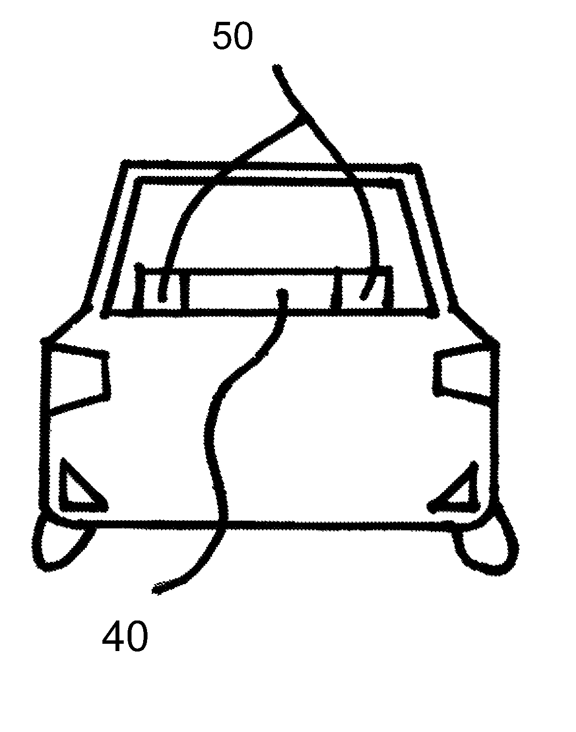
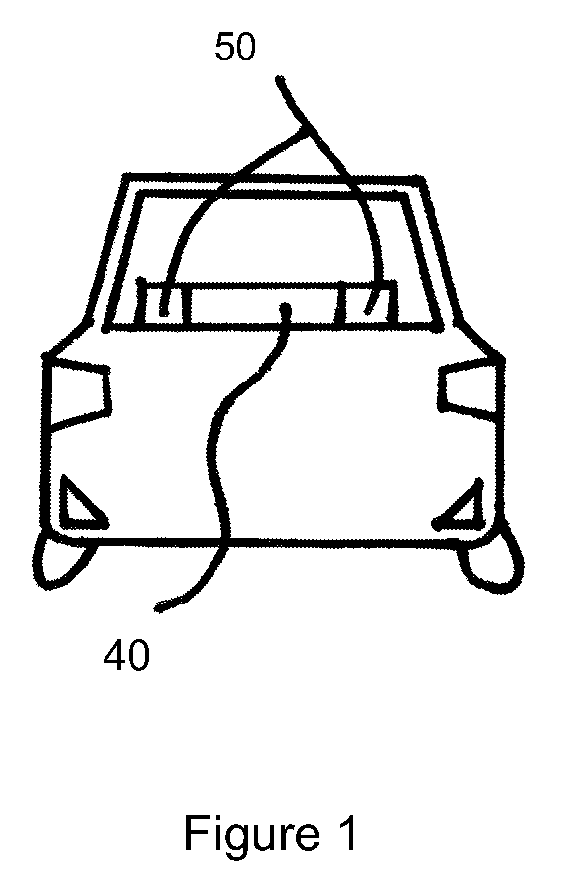
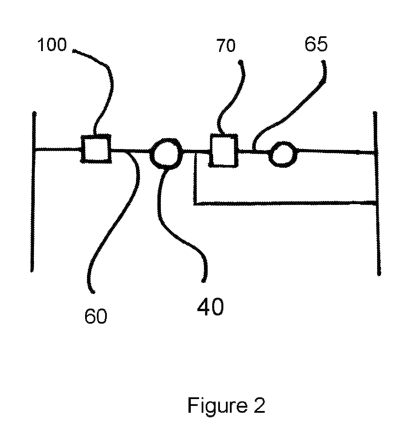
[0025]The present invention is an abrupt braking indicator that is designed to complement existing brake lights of a vehicle by warning drivers following behind the vehicle of an abrupt stop or other emergent-braking conditions as opposed to the mere common use of the brakes for slowing down or turning. The Abrupt-Braking Indicator (ABI) is adaptable to virtually all types of vehicles in respect to its placement and installment. Moreover, the present invention consists of a relatively simple construction, which aids in its durability and installment while maximizing its desired effect. The present invention is made of a conventional switch mechanism that activates a flashing light at or above 0.5 G and an electrical connection that can feed off of the existing connection to the vehicle's third brake light or any other power supply.

[0026]FIG. 1 shows the two flashing strobe lights (50) lit to demonstrate their distinct brightness and color in conjunction with the existing third brake...


PUM


Abstract

An Abrupt Braking Indicator (ABI) that complements a vehicle's existing rear brake light by determining the difference between regular brake pedal usage and dangerous abrupt stops or abrupt-braking that often causes accidents. It is when, and only when, an abrupt stop or hard brake occurs at the differential gravitational value of 0.5 G or more that the present invention emits highly noticeable flashing lights that warn following drivers of the sudden hazard ahead.

Description

FIELD OF THE PRESENT INVENTION[0001]The present invention is a vehicle warning system relating to automotive braking lights. In particular, the present invention relates to brake lights that indicate the abrupt-braking of the vehicle in which they are installed.BACKGROUND OF THE PRESENT INVENTION[0002]In 2002 there were 42,815 fatalities on U.S. highways, according to the U.S. Department of Transportation.1 Given the high speeds at which drivers travel on U.S. highways, and even local roads, the difference between an accident and a close call can often be measured in split seconds. Many times, it is our conditioned reflexes that take control in emergency driving conditions. In such cases, allowing drivers a few more moments in which to react may save numerous lives and prevent needless property damage. 1 http: / / safety.fhwa.dot.gov / facts / stats2002 / index.htm#map1[0003]Data from the year 2000 indicates that there are 1.5 million rear-end collisions each year, which account for approxim...

Claims


Application Information

Patent Timeline
Patent Type & Authority Patents(United States)
IPC IPC(8): B60Q1/52
CPCB60Q1/447
Inventor MALIK, MOHD B.
Owner MALIK MOHD B
Why Eureka
Try Eureka