Roll stiffness control apparatus of vehicle

a technology of rolling stiffness control and vehicle, which is applied in the direction of position/direction control, animal undercarriage, special data processing applications, etc., can solve the problems of not taking into account the force generated by each wheel, and achieve the effect of improving the turning limit of the vehicle, and reducing the remaining capacity

Inactive Publication Date: 2011-11-01
TOYOTA JIDOSHA KK
View PDF37 Cites 21 Cited by
  • Summary
  • Abstract
  • Description
  • Claims
  • Application Information

AI Technical Summary

Benefits of technology

[0009]According to an aspect of the invention, there is provided a roll stiffness control apparatus of a vehicle, including a controller which estimates a remaining capacity of front wheels to generate a lateral force and a remaining capacity of rear wheels to generate a lateral force, and which sets a roll stiffness distribution ratio between the front wheels and the rear wheels so as to reduce a difference between the remaining capacity of the front wheels to generate the lateral force and the remaining capacity of the rear wheels to generate the lateral force.
[0010]According to another aspect of the invention, there is provided a roll stiffness control apparatus of a vehicle, including roll stiffness distribution ratio changing means for changing a roll stiffness distribution ratio between front wheels and rear wheels; remaining capacity estimating means for estimating a remaining capacity of the front wheels to generate a lateral force and a remaining capacity of the rear wheels to generate a lateral force; and control means for controlling the roll stiffness distribution ratio changing means so as to reduce a difference between the remaining capacity of the front wheels to generate the lateral force and the remaining capacity of the rear wheels to generate the lateral force.
[0011]With the roll stiffness control apparatus having the above-mentioned structure, the roll stiffness distribution ratio between the front wheels and the rear wheels is controlled such that the difference between the remaining capacity of the front wheels to generate a lateral force and the remaining capacity of the rear wheels to generate a lateral force is reduced. Therefore, the remaining capacity of one of the front wheels and the rear wheels, which have the lower remaining capacity, can be increased, and the remaining capacity of the other of the front wheels and the rear wheels, which have the higher remaining capacity, can be decreased. Accordingly, as compared with the case where the difference between the remaining capacity of the front wheels to generate a lateral force and the remaining capacity of the rear wheels to generate a lateral force is not reduced, the lateral force of the entire vehicle can be increased, and the turning limit of the vehicle can be improved.

Problems solved by technology

However, in the above-mentioned conventional type of roll stiffness control apparatus, a force which can be generated by each wheel is not taken into account.

Method used


Image

  • Roll stiffness control apparatus of vehicle
  • Roll stiffness control apparatus of vehicle
  • Roll stiffness control apparatus of vehicle

Examples


Embodiment Construction

[0021]In the following description and the accompanying drawings, the present invention will be described in more detail with reference to an exemplary embodiment.

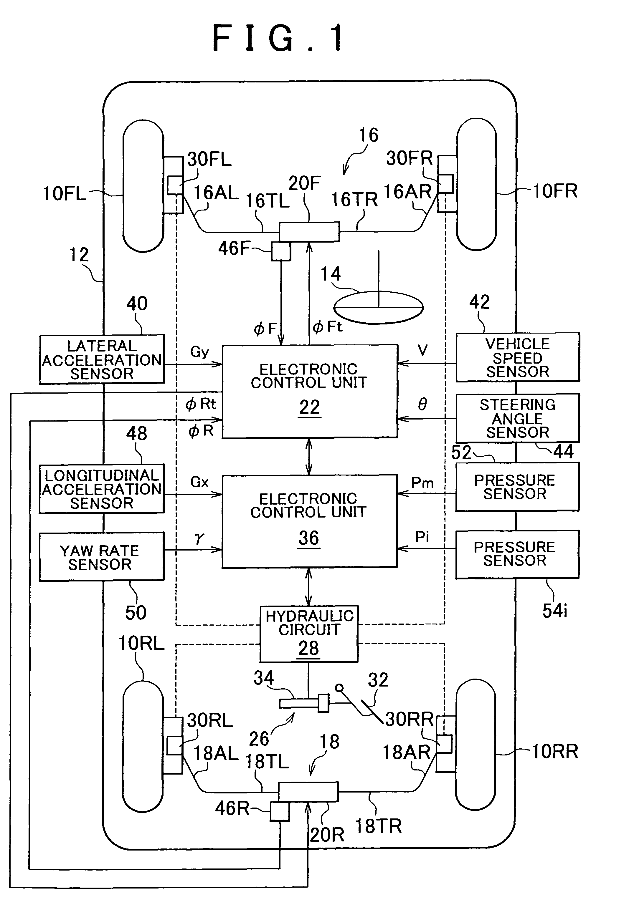
[0022]FIG. 1 is a view schematically showing a structure of a roll stiffness control apparatus of a vehicle according to an embodiment of the invention, which is applied to a vehicle provided with an active stabilizer unit on each of a front wheel side and a rear wheel side.

[0023]In FIG. 1, a reference numeral “10FR” indicates a right front wheel of a vehicle 12, a reference numeral “10FL” indicates a left front wheel of the vehicle 12, a reference numeral “10RR” indicates a right rear wheel of the vehicle 12, and a reference numeral “10RL” indicates a left rear wheel of the vehicle 12. The right and left front wheels 10FR and 10FL that serve as steering wheels are driven, via a tie rod, by a power steering device (not shown) that is driven when a driver turns a driver's wheel 14. The roll stiffness control apparatus accor...


PUM


Abstract

A roll stiffness control apparatus of a vehicle, which includes a controller that estimates a remaining capacity of front wheels to generate a lateral force and a remaining capacity of rear wheels to generate a lateral force, and that sets a roll stiffness distribution ratio between the front wheels and the rear wheels so as to reduce a difference between the remaining capacity of the front wheels to generate a lateral force and the remaining capacity of the rear wheels to generate a lateral force.

Description

INCORPORATION BY REFERENCE[0001]The disclosure of Japanese Patent Application No. 2004-200339 filed on Jul. 7, 2004, including the specification, drawings and abstract is incorporated herein by reference in its entirety.BACKGROUND OF THE INVENTION[0002]1. Field of the Invention[0003]The invention relates to a roll stiffness control apparatus of a vehicle. More particularly, the invention relates to a roll stiffness control apparatus of a vehicle, which controls a roll stiffness distribution ratio between front wheels and rear wheels based on a remaining capacity of the front wheels to generate a lateral force and a remaining capacity of the rear wheels to generate a lateral force such that the roll stiffness distribution ratio between the front wheels and the rear wheels is changed to an appropriate value.[0004]2. Description of the Related Art[0005]Japanese Patent Application Publication No. JP(A) 06-211018 discloses a known roll stiffness control apparatus of a vehicle, for exampl...

Claims


Application Information

Patent Timeline
Patent Type & Authority Patents(United States)
IPC IPC(8): G06F7/00
CPCB60G17/0162B60G17/0182B60G17/0195B60G21/0555B60W10/184B60W10/22B60W30/045B60G2202/40B60G2204/81B60G2204/82B60G2204/8302B60G2400/051B60G2400/0523B60G2400/104B60G2400/106B60G2400/204B60G2400/25B60G2400/41B60G2400/50B60G2600/187B60G2800/012B60G2800/0122B60G2800/214B60G2800/24B60G2800/91B60G2800/922
Inventor MIZUTA, YUICHI
Owner TOYOTA JIDOSHA KK
Why Eureka
Try Eureka