Method of maintaining a bowling lane

a maintenance machine and bowling lane technology, applied in bowling games, suction cleaners, construction, etc., can solve the problems of unwieldy supply cords and long currents in the house, and achieve the effect of sacrificing quality and speed

Active Publication Date: 2011-11-08
KEGEL LLC
View PDF88 Cites 7 Cited by
  • Summary
  • Abstract
  • Description
  • Claims
  • Application Information

AI Technical Summary

Benefits of technology

[0003]In a machine constructed in accordance with the principles of the present invention the operational steps of the machine are such that battery operation can become a practical reality, without sacrificing quality and speed. Although the inventive operating steps are beneficial even if not incorporated into a machine that is battery-powered, the convenience of battery operation makes incorporating these principles into a battery-powered machine particularly attractive.

Problems solved by technology

In the past, such machines have required connection to house current through a long, unwieldy supply cord because the sequence of operations performed by the machine drew too much electrical current to make battery operation practical considering the significant number of lanes in a bowling facility.

Method used


Image

  • Method of maintaining a bowling lane
  • Method of maintaining a bowling lane
  • Method of maintaining a bowling lane

Examples


Embodiment Construction

[0013]The present invention is susceptible of embodiment in many different forms. While the drawings illustrate and the specification describes certain preferred embodiments of the invention, it is to be understood that such disclosure is by way of example only. There is no intent to limit the principles of the present invention to the particular disclosed embodiments.

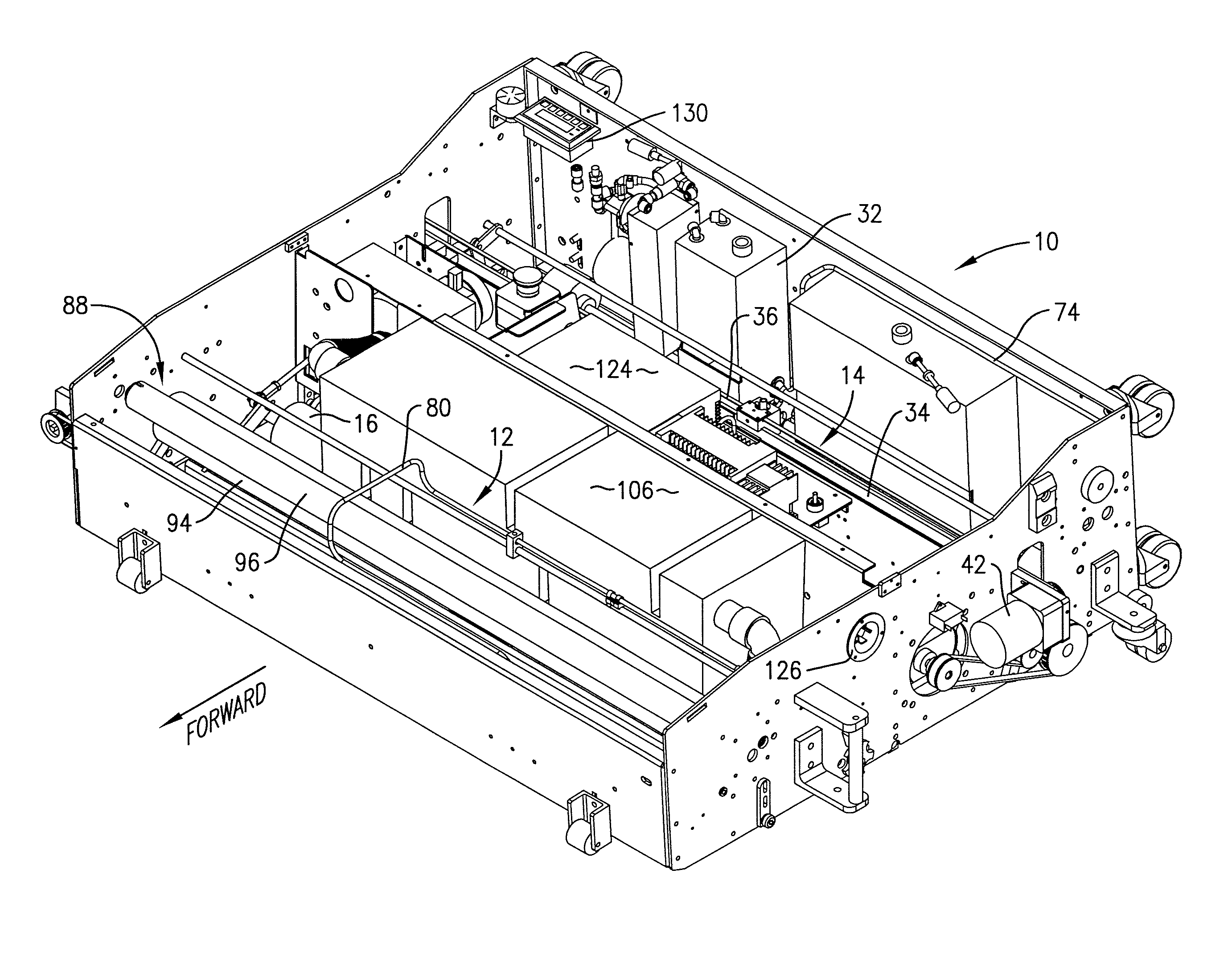
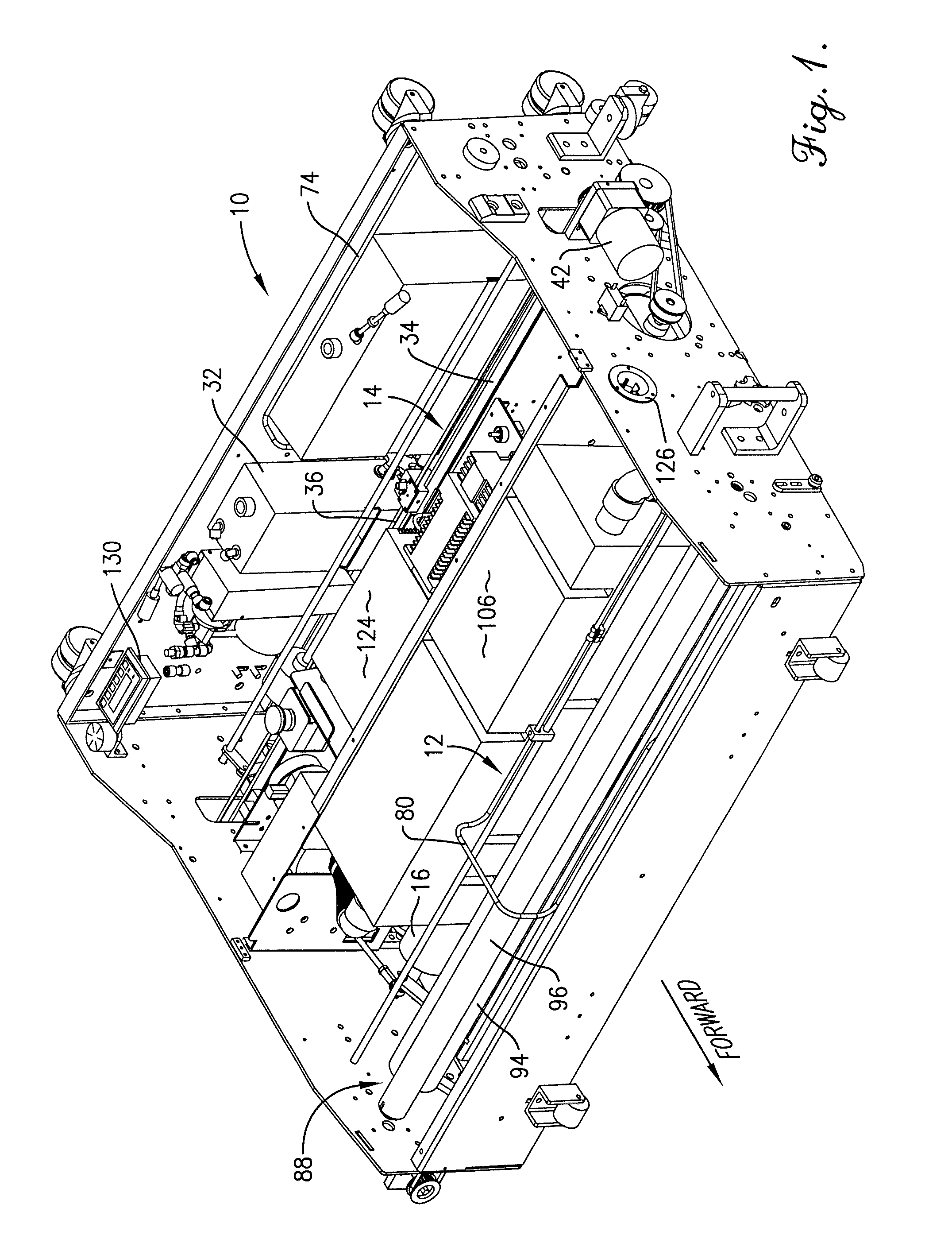
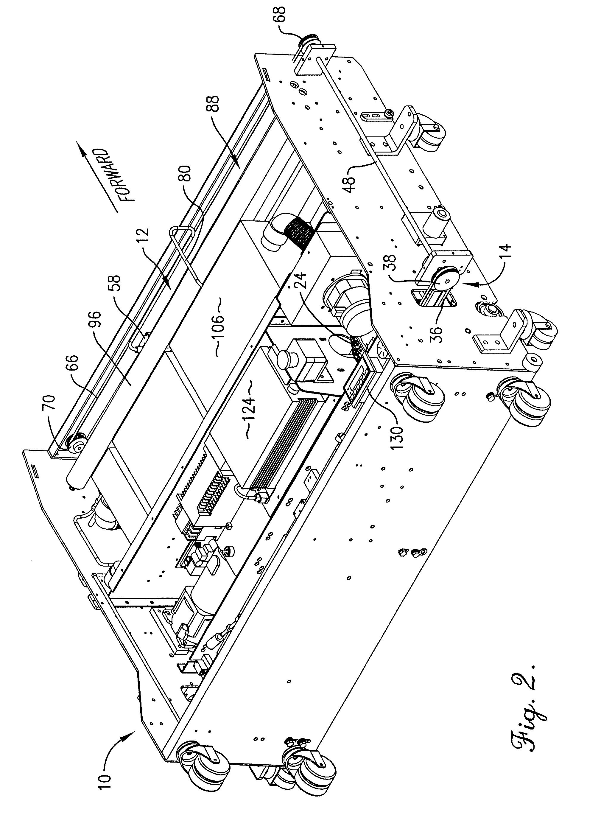
[0014]The machine 10 illustrated in the drawings is similar in many respects to the machine disclosed in U.S. Pat. No. 5,729,855 and U.S. Pat. No. 6,939,404. Accordingly, the '855 and '404 patents are hereby incorporated by reference into the present specification. In view of the full disclosure in the '855 and '404 patents of the construction and operation of the lane machine, the construction and operation of the machine 10 will be described only generally herein.

[0015]The machine 10 has a cleaning system denoted broadly by the numeral 12 and located generally in the front of the machine. A dressing (preferably oil) ...


PUM


Abstract

A bowling lane maintenance machine has its operating functions designed and controlled in such a manner that the machine may be battery-operated without loss of performance. Included in the operation are special movements of the machine at the pin deck to flick moisture off blades of the squeegee assembly and limited activation of the vacuum motor to reduce battery drain.

Description

TECHNICAL FIELD[0001]The present invention relates to the field of bowling lane maintenance machines, in particular, to machines that can both clean and dress the lanes as they move along the surface thereof. It relates especially to a machine whose various operating functions are carried out in such a manner as to render the machine suitable for, but not necessarily limited to, battery operation so as to eliminate the need for an electrical supply cord connecting the machine to a source of electrical house current.BACKGROUND AND SUMMARY[0002]It is well known in the prior art to provide a lane machine that applies cleaning liquid to the lane at the front of the machine, picks up the liquid, surface grime and old dressing (oil) near the middle of the machine, and then applies a new film of oil to the cleaned surface at the rear of the machine as the machine is traveling along the length of the lane. In the past, such machines have required connection to house current through a long, ...

Claims


Application Information

Patent Timeline
Patent Type & Authority Patents(United States)
IPC IPC(8): A47L11/10
CPCA63D5/10
Inventor DAVIS, MARK E.DAVIS, JOHN M.
Owner KEGEL LLC
Why Eureka
Try Eureka