
Loudspeaker with piezoelectric elements

a piezoelectric element and loudspeaker technology, applied in the direction of electrical transducers, electrical transducers, transducer types, etc., can solve the problems of increasing the size, weight, and cost of the associated loudspeaker, and reducing the power efficiency of the amplifier, so as to reduce the weight and cost, reduce the cost of the amplifier, and eliminate the effect of bulky magnets

Active Publication Date: 2015-08-27
HARMAN INT IND INC
View PDF9 Cites 0 Cited by
  • Summary
  • Abstract
  • Description
  • Claims
  • Application Information

AI Technical Summary

Benefits of technology

The patent describes a way to make sound using piezoelectric actuators instead of traditional magnets. This method eliminates the need for big, expensive magnets and improves efficiency. By driving the membrane of the loudspeaker at a specific area, the vibrations of the actuator are distributed evenly along the membrane. This results in a thinner and lighter loudspeaker that maintains good sound quality. Overall, this patent presents a way to make a high-quality loudspeaker that's lighter, more efficient, and cheaper.

Problems solved by technology

Such electroacoustic transducers may be bulky and costly, thereby increasing the size, weight, and cost of the associated loudspeaker.

Method used


Image

  • Loudspeaker with piezoelectric elements
  • Loudspeaker with piezoelectric elements
  • Loudspeaker with piezoelectric elements

Examples


first embodiment

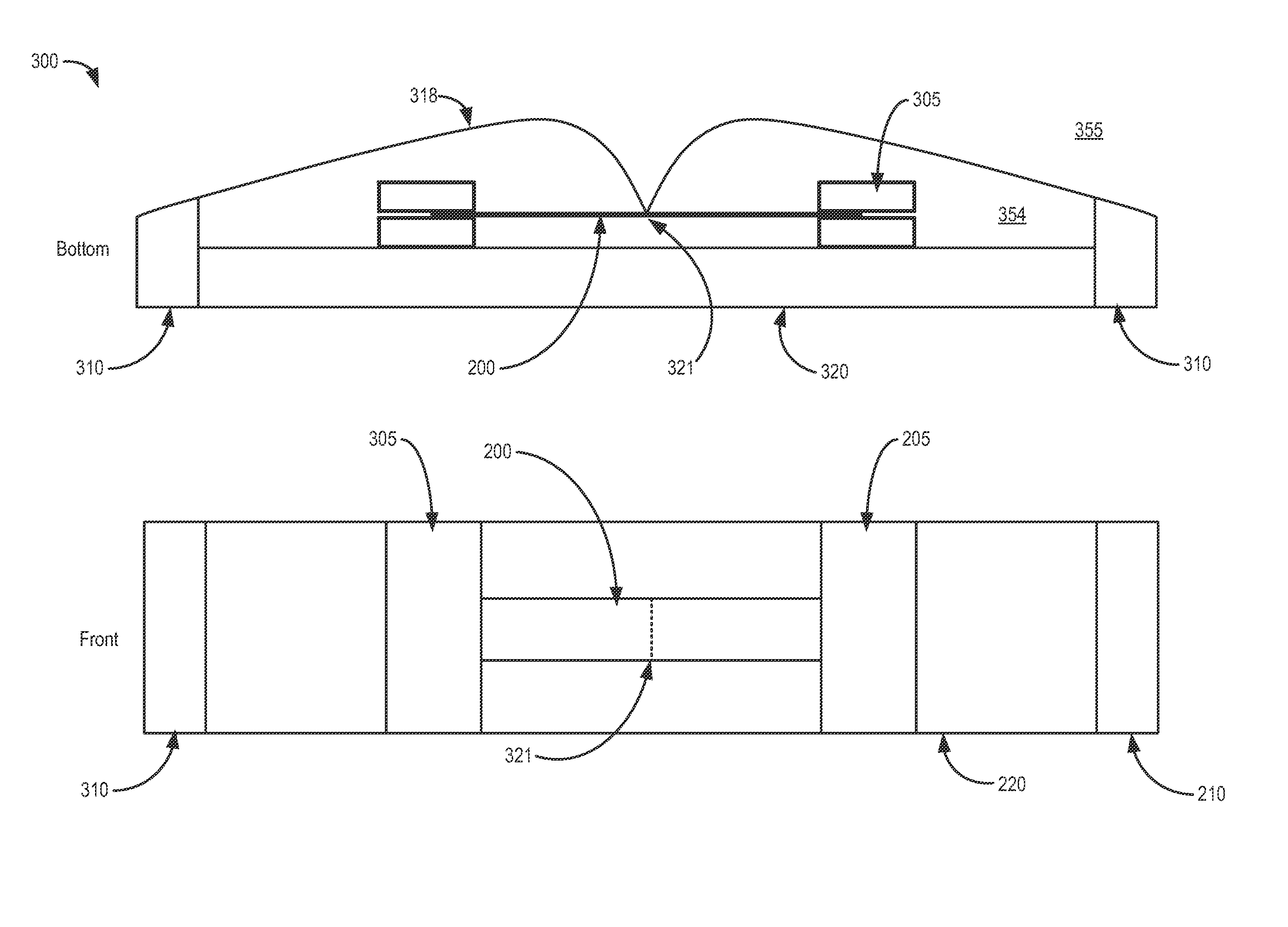
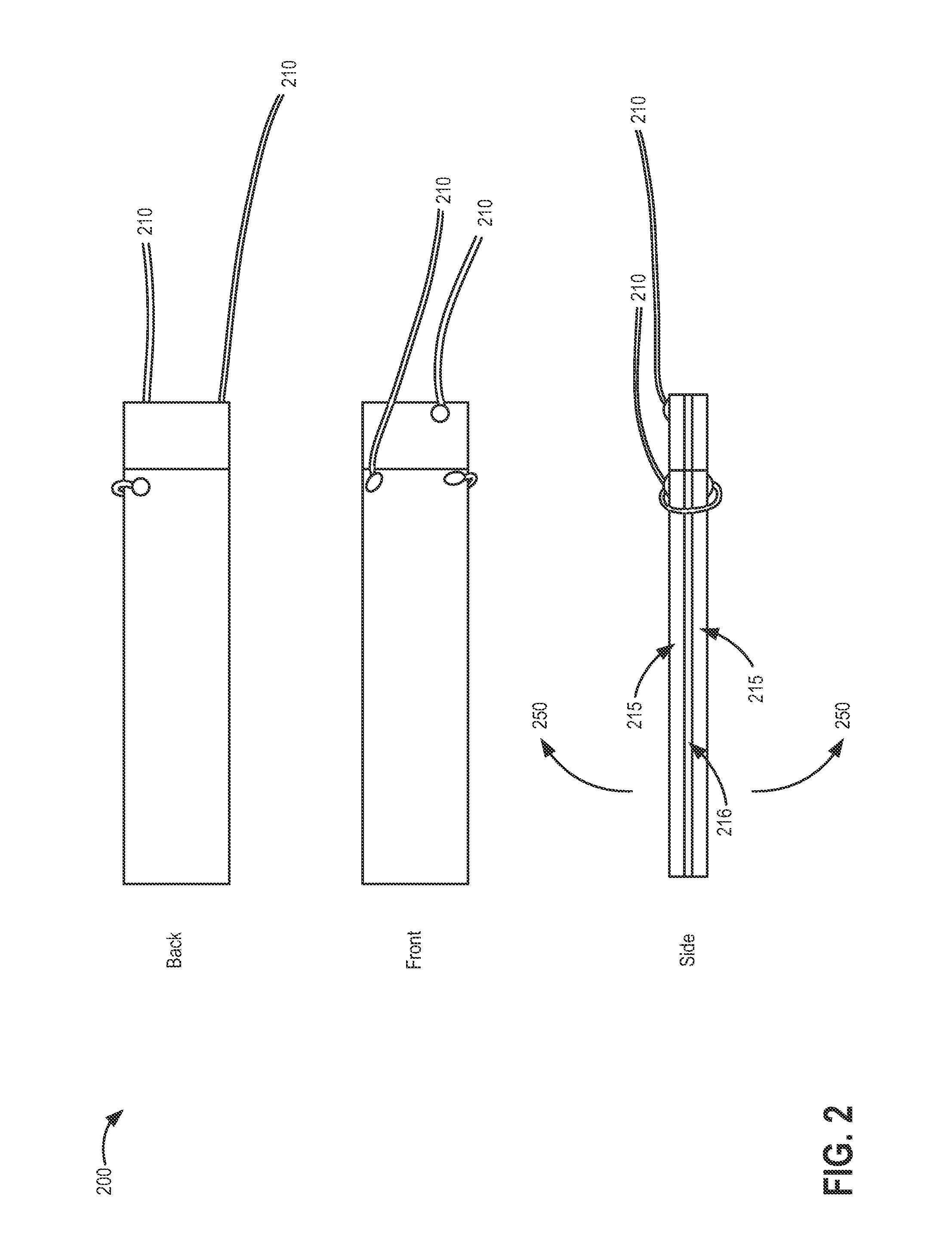
[0028]As opposed to rigidly fixing one end of a bimorph actuator, sound quality may be enhanced by fixing the bimorph on both ends and allowing the bimorph to move in between the two fixed ends. a single element 300 of a piezoelectric speaker is shown in FIG. 3, where the element is fixed on both ends. Two views of element 300 are shown, including a front view and a bottom view, as labeled. Throughout this description, the piezoelectric element 300 forms the basis for any speaker system described. A plurality of elements 300 may be combined and arranged to form element arrays that may be wired to produce coherent sound. As seen, a bimorph 200 is clasped on both ends by grips 305 (e.g., each grip being attached to a different, opposing end of the bimorph 200). While the bimorph 200 illustrated in FIG. 3 corresponds to the bimorph 200 of FIG. 2, it is to be understood that any suitable piezoelectric actuator may be utilized where bimorph 200 is referenced in the disclosure. The grips ...

second embodiment

[0043]a piezoelectric loudspeaker is shown in FIG. 14, illustrated as a wiring scheme with various electrical elements. As opposed to loudspeaker 1000 that directs the mid-high frequencies to five bimorph actuators 200, speaker 1400 divides the five actuators such that one handles all high frequency sounds in a high-frequency circuit 1495 while the other four handle the low frequency sounds in a low-frequency circuit 1490. An incoming audio signal from external audio source 1481 is separated into two bands by the frequency-dividing network of a crossover 1483. One band may contain the low frequency signal while the other band may contain the high frequency signal, where the division between low and high frequencies is relative depending on a pre-determined frequency. As an example, one band (low band) may comprise frequencies ranging from 200 Hz to 2 kHz, while the second band (high band) may comprise frequencies ranging from 2 kHz to 20 kHz. In this case, 2 kHz would be the pre-det...


PUM


Abstract

Embodiments are disclosed for a loudspeaker driven by one or more piezoelectric actuators. In embodiments of the disclosure, a loudspeaker comprises a support structure, and a piezoelectric layered cantilever actuator affixed to the support structure via at least two grips. The support structure may also comprise a membrane suspended over the piezoelectric actuator, the membrane being in contact with the piezoelectric actuator between the at least two grips.

Description

FIELD[0001]The disclosure relates to efficient audio transducers utilizing piezoelectric materials and elements to produce audio sounds.BACKGROUND[0002]In a transducer, energy of one form is converted to energy of a different form. Some loudspeakers may utilize electroacoustic transducers that convert electrical impulses to acoustic vibrations that may be perceived as audible sound to proximate listeners. Conventional electroacoustic transducers, or speaker drivers, include a conical diaphragm and frame with the magnetic sound-producing components mounted to the small end of the cone, leaving the large end of the cone open. Such electroacoustic transducers may be bulky and costly, thereby increasing the size, weight, and cost of the associated loudspeaker. Loudspeakers utilizing piezoelectric transducers typically provide a reduced frequency response and increased distortion compared to other types of transducers (e.g., electroacoustic transducers including magnetic components) due ...

Claims


Application Information

Patent Timeline
IPC IPC(8): H04R17/00
CPCH04R17/00H04R1/403H04R3/00H04R17/005H04R17/02H04R17/025H04R2217/00H04R2217/01H04R2217/03
Inventor HORBACH, ULRICH
Owner HARMAN INT IND INC
Learn More