Primary and counter knife assembly for use in wood chipper

a wood chipper and primary technology, applied in the field of wood chippers, can solve the problems of inefficiency of counter knife devices, inability to further reduce the size of individual wood chip slices, and inability to be used in downstream processing units, etc., to achieve the effect of reducing the size of chips and reducing the size of each sli

Active Publication Date: 2011-11-08
CEM MACHINE
View PDF78 Cites 12 Cited by
  • Summary
  • Abstract
  • Description
  • Claims
  • Application Information

AI Technical Summary

Benefits of technology

[0006]It is therefore an object of the present invention to improve the design of rotary disc wood chippers.
[0010]These and further objects of the present invention are attained by a counter knife system that is mounted within each of the chip slots of a rotary disc chipper. The system includes a first series of spaced apart chip contact elements having a first height that are mounted in each chip slot for engaging chip slices coming off the primary knife to reduce the size of each slice. A further second series of spaced apart chip contact elements having a second height that is less than that of the first chip contact elements in the first series that are arranged to contact the chips leaving the first series of chip contact elements to further reduce the size of the chips.

Problems solved by technology

As a result, these wood chip slices often do not lend themselves for use in downstream processing units without further reduction of the size of the individual wood chip slices.
Most machines for further reducing the size of the wood chips consume a substantial amount of energy.
These counter knife devices are generally not very efficient and fail to utilize a substantial portion of the energy that is carried by the chip slices leaving the primary chipping knife.

Method used


Image

  • Primary and counter knife assembly for use in wood chipper
  • Primary and counter knife assembly for use in wood chipper
  • Primary and counter knife assembly for use in wood chipper

Examples


Embodiment Construction

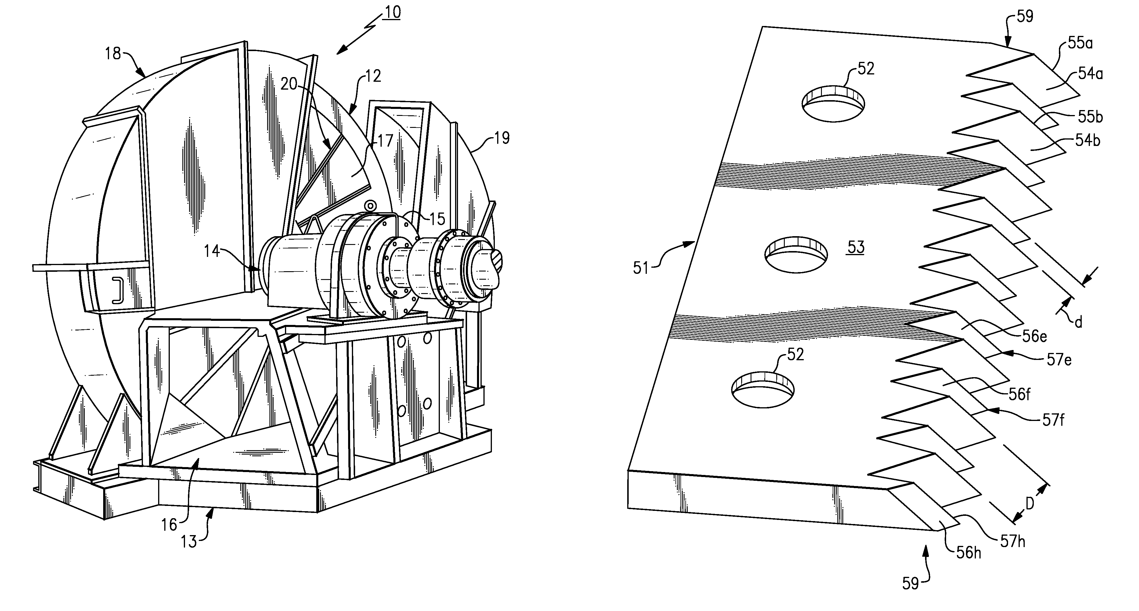
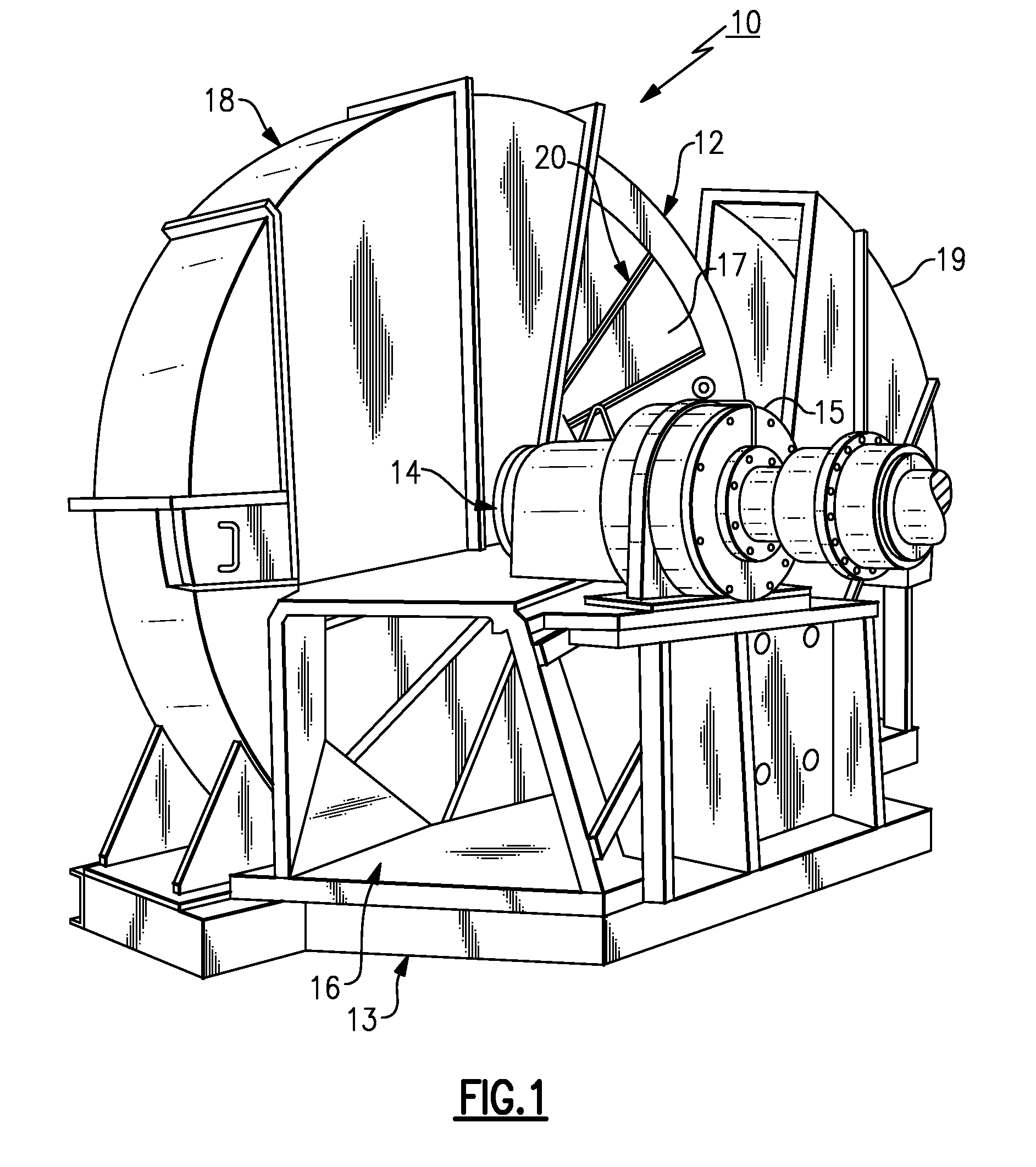
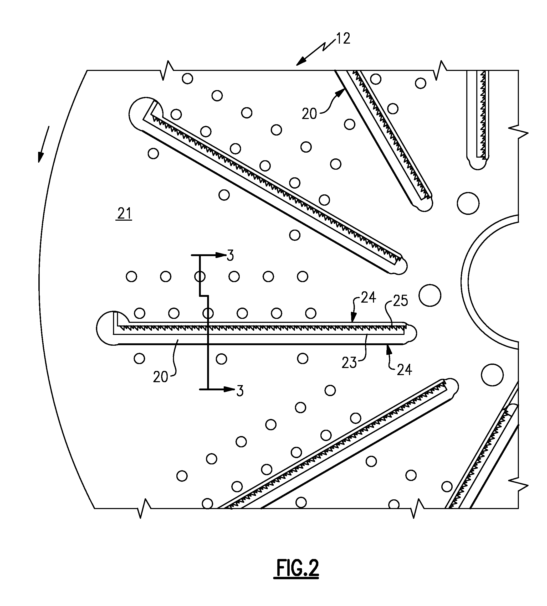
[0025]Turning initially to FIGS. 1-7, there is illustrated a wood chipper generally referenced 10, that embodies the present invention. The wood chipper includes a rotary disc 12 that is supported upon a horizontal shaft 14 within the machine frame. The shaft 14 is supported by a bearing 15 that is mounted upon the frame 13 and driven by a motor (not shown). The motor drives a shaft that is coupled to the horizontal shaft 14 of the wood chipper. A horizontally disposed feed spout 16 is located below the shaft 14 and arranged to conduct wooden work pieces into contact with the front face 17 of the disc. The disc is enclosed within a protective casing generally referenced 18. A portion of the casing 19 is shown moved back in FIG. 1 to reveal the front face 17 of the disc. A series of spaced apart, radially disposed chip slots 20 are formed through the disc between the front face 17 and the rear face 21 (FIG. 3) of the disc.

[0026]As best illustrated in FIGS. 2-4, a primary chipper knif...


PUM


Abstract

A wood chipper having a rotatable disc that contains a series of slots that pass through the disc. A primary chipper knife is located at the entrance of each slot which separates slices from a work piece and directs the slices through the slot. A counter knife unit is mounted within each slot for engaging the slices leaving the primary chipper knife to reduce the size of the chips as they move through the slot. The counter knife unit contains a first series of spaced apart chip contact elements that have a first height to contact the slices as they leave the primary chipper knife to reduce the size of the slices. The counter knife further contains a second series of chip contact elements that have a second height that is less than that of the chip contact element in the first series. Each contact element in the second series is arranged to contact chips leaving the contact elements in the first series to further reducing the size of the chips.

Description

CROSS REFERENCE TO PATENT APPLICATIONS INCLUDING RELATED SUBJECT MATTER[0001]This patent application includes subject matter that is related to subject matter that is included within U.S. patent application Ser. No. 12 / 401,930 now U.S. Pat. No. 7,896,268 and titled “Apparatus for Producing Small Size Wood Chips”, filed Mar. 11, 2009.[0002]This patent application also includes subject matter that is related to subject matter that is included within U.S. patent application Ser. No. 11 / 503,811 now U.S. Pat. No. 7,669,621 and titled “Stationary Bedknife For Disc Chipper Apparatus”, filed Aug. 14, 2006.FIELD OF THE INVENTION[0003]This invention relates generally to a wood chipper and more specifically to an improved counter knife for enhancing the quality of wood chips produced from operation of a disc type wood chipper.BACKGROUND OF THE INVENTION[0004]Disc wood chippers typically contain a shaft 14 for rotating a disc about a horizontal axis. The disc typically includes a plurality of r...

Claims


Application Information

Patent Timeline
Patent Type & Authority Patents(United States)
IPC IPC(8): B27C1/00B02C19/00B27L11/00
CPCB27L11/005
Inventor ROBINSON, MARK D.BOLIVER, SCOTT J.
Owner CEM MACHINE
Why Eureka
Try Eureka