Linear bearing

Inactive Publication Date: 2011-11-08
APA PARAFRICTA
View PDF15 Cites 7 Cited by
  • Summary
  • Abstract
  • Description
  • Claims
  • Application Information

AI Technical Summary

Benefits of technology

[0012]Because the present invention provides an excellent solution to the reduction of frictional forces between two bodies which are required to be or inevitably will move relative to each other, the invention may be applied to both rectilinear and curvilinear including sphericolinear situations where the bodies which require to move relative to each other can be enabled to move either two or three dimensionally relative to each other. Take, for example, in tidal waters, where a ship is moored alongside a jetty, a gangway is provided to access the ship from the jetty. In such a case, the ship moves relatively to the jetty up and down and to an extent along the jetty and slightly towards or away from the jetty. In such a case, it is conventional to secure the gangway to the ship in such a way that the inboard end can move in a vertical plane and slightly pivot in the horizontal plane whilst the outboard or jetty end can move both in a vertical plane and move in the horizontal plane. Such movement which is allowed for is however subject to restraint by inboard tackles and needs to be watched by gangway staff. A similar problem arises when accessing pontoons.

Problems solved by technology

Both methods of placing the patient on the stretcher are dangerous since spinal injuries can be aggravated by the action of lifting or rolling.

Method used


Image

  • Linear bearing
  • Linear bearing
  • Linear bearing

Examples


Embodiment Construction

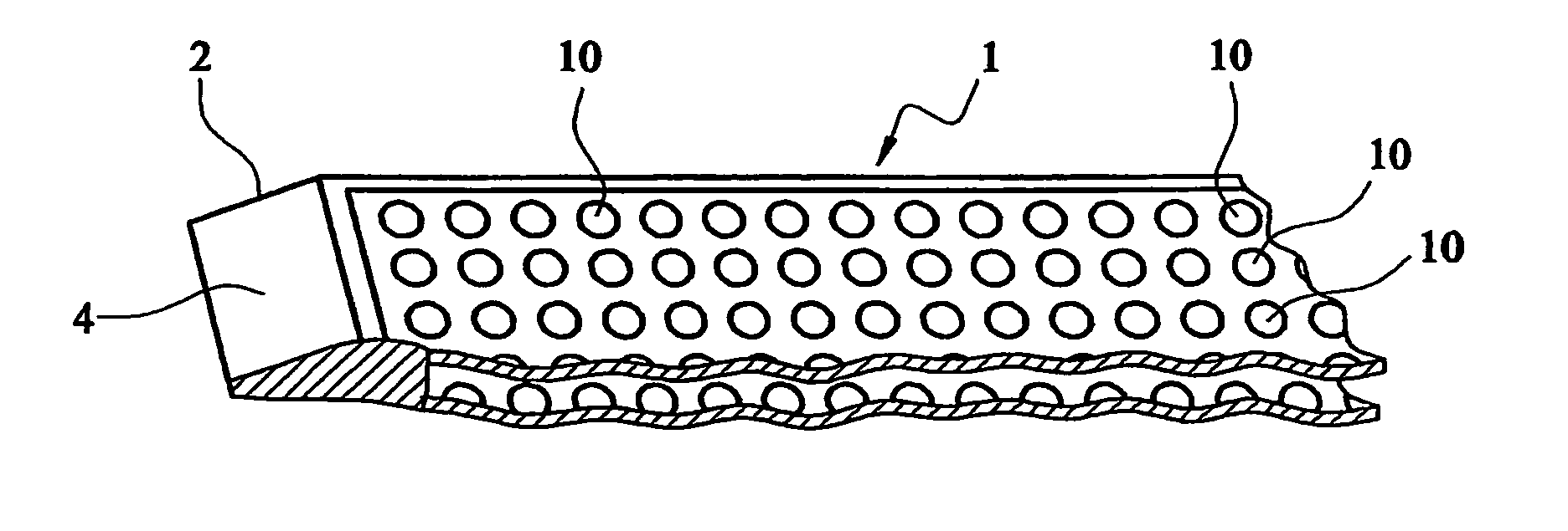
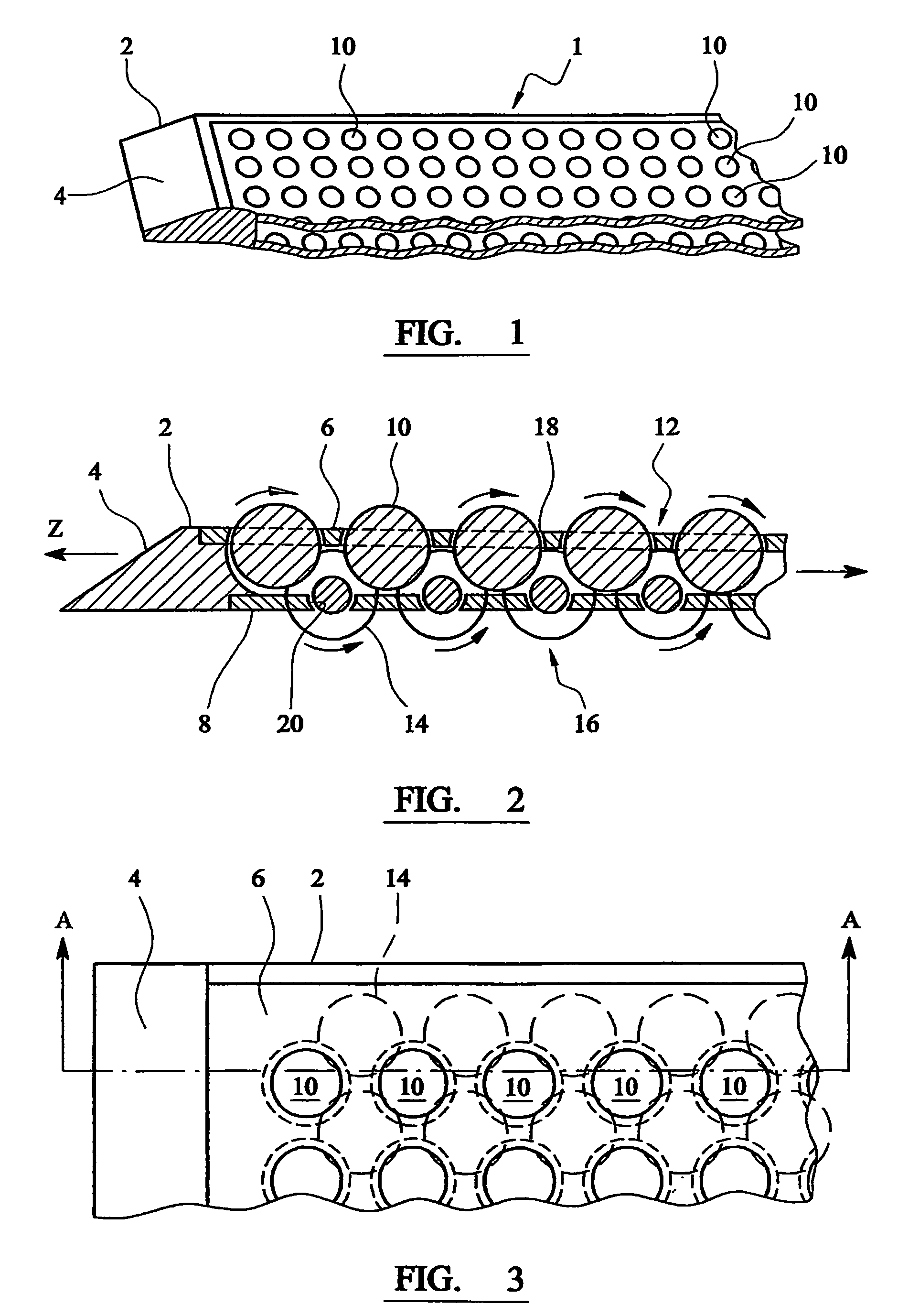
[0026]The bearing in the form of a mat of FIG. 1 is formed with a frame 2 made of a flexible plastics material having a chamfered edge 4 and supporting an upper perforated sheet 6 and a lower perforated sheet 8. The upper perforated sheet locates a plurality of spheres 10 and together they form a first matrix 12. The lower perforated sheet 8 locates rows of spheres 14 which form a second matrix 16. The upper rows of spheres 10 of the first matrix seat on the lower spheres of the second matrix in such a way that most of the upper spheres each are supported on four lower spheres.

[0027]The upper spheres 10 located in perforations 18 of sheet 6 are such as to allow free rotation of spheres 10. Similarly, perforations 20 in lower sheet 8 allow free rotation of spheres 14. Since the upper spheres are seated on the lower spheres, any rotation of the lower spheres will cause counter rotation of the upper spheres. In this way, any movement of bearing 1 when placed on the ground will cause th...


PUM


Abstract

A bearing (1) having a frame (2), the frame at least partly surrounding two matrices (12, 16), each of a plurality of spheres (10) which are mounted for rotation so that the spheres in each matrix when the matrix is flat lie in a substantially single plane, the plane of one matrix being parallel to that of the other, the spheres of one matrix are so located that they mostly lie against the spheres on the other matrices so that rotation of the spheres of one matrix results in counter-rotation of spheres of the other matrix; the bearing formed in such a way enables the beating to be pushed or pulled under an object such as a patient lying on the ground with little or no movement transmitted to the object / patient as the bearing moves between the object and an underlying surface. The bearing can also be used for massaging a patient who is unable to move his or her body or for bearings with civil engineering applications.

Description

CROSS REFERENCE TO RELATED APPLICATIONS[0001]The present application is the U.S. national phase entry of PCT / GB2003 / 004470 with an international filing date of Oct. 14, 2003 and claims priority from GB Patent Application Serial No. 0223707.1, filed Oct. 14, 2002 and issued as GB Patent No. 2394423 on Sep. 22, 2004.FIELD OF THE INVENTION[0002]The present invention relates to linear bearings.BACKGROUND OF THE INVENTION[0003]Linear bearings are used for a number of purposes, for instance ball conveyors as shown in GB Patent No 543,524 (Curran) and GB Patent No 1,263,456 (NRDC). The principle 8 of ball conveyors has been used for moving loads such as boxes or work pieces and also for patients in a hospital.[0004]The present invention is also designed in different forms to cope with the problem of moving objects of the same width as above including heavy structures like bridge components as well as for handling patients.[0005]Rescue stretchers are either rigid or flexible and are normall...

Claims


Application Information

Patent Timeline
IPC IPC(8): F16C29/00F16C19/20A61G1/003A61G7/10A61G7/14B65G39/02
CPCA61G1/003A61G7/1011A61G7/103A61G7/1034A61G7/1057B65G39/025F16C19/20F16C29/046A61G7/1069A61G7/1076A61G2200/32F16C29/00A61G7/10
Inventor PIKE, ANTHONY BRUCE
Owner APA PARAFRICTA
Why Eureka
Try Eureka