Shape reconstruction using X-ray images

a technology of x-ray images and reconstruction, applied in the field of medical imaging, can solve the problems of increased radiation load on patients, high cost of devices, and system failure to meet the required accuracy of the respective patient to be treated

Active Publication Date: 2011-11-08
BRAINLAB +1
View PDF16 Cites 31 Cited by
  • Summary
  • Abstract
  • Description
  • Claims
  • Application Information

AI Technical Summary

Benefits of technology

[0015]Preferably, only rigid matching is performed to find a best or at least a good orientation of the three-dimensional model relative to the at least one two-dimensional image. Elastic matching is performed preferably only after the orientation of the three-dimensional model has been determined to fit the projection of the three-dimensional model to the two-dimensional image. Rigid matching can be performed as a first step, while elastic matching, including the deformation of the three-dimensional model, preferably is conducted only after the best or a good orientation or position of the three-dimensional model in relation to the two-dimensional image is found. The rigid matching itself can use an iterative approach, wherein the elastic matching, which can be more complicated to perform, can directly calculate the shape deformation in a single step, thus saving time.
[0016]The image-to-model correspondence establishing algorithm described herein is not only faster than conventional methods, but also improves the robustness with respect to certain outliers and automatic exclusion of cross matching, which is an important property for the preservation of the topology.
[0026]For the fast extraction of a smooth apparent contour from a given surface model, the approach introduced by Hertzmann and Zorin, described in Hertzmann A. and Zorin D.: Illustrating smooth surfaces. In SIGGRAPH, (2000), 517-526, which is hereby incorporated by reference, can be used. This approach first constructs a dual representation of the given surface mesh in a four-dimensional (4D) space based on the position and tangent planes of every vertex. The focal point's dual (a plane in 4D) intersects with the mesh triangle's dual. Beforehand, the approach normalizes the dual vertices using the I∞ norm so that the vertices end up on one of the unit hypercube's sides. This reduces the problem to intersecting the triangles on a hypercube's side with the focal point's dual plane, i.e., to intersect triangles in eight 3D unit cubes (the eight hypercube sides) with a plane. By using Octree for each hypercube side, the extraction process can be greatly sped up. An example is given in FIG. 4.
[0028]Following the general framework of point matching described in Chui H., Rambo J., Duncan J., Schultz R., and Rangarajan A.: Registration of cortical anatomical structures via robust 3D point matching. In: IPMI '99, Lecture Notes in Computer Science, Vol. 1613, Springer (1999): 168-181, which is hereby incorporated by reference, the 2D matching can be considered as a two-stage process: correspondence and spatial mapping. TPS can be used here for parameterization of the spatial mapping. But unlike described in Chui H., et al., the correspondence problem can be solved differently. To make the description simple, the detected edge pixels in image s are denoted as Is={Isi, i=1, 2, . . . , N} and the 2D projection of the apparent contours as As={Asj, j=1, 2, . . . , M}. Here the 2D matching in one image is focused. The overall correspondence can be established by combining matched point pairs found in all input images.
[0044]A. Compute a 2D TPS-based spatial mapping f using the estimated set of SINs by minimizing the following cost function:
[0051]Based on the estimated scale and pose information from the first stage, the correspondence establishing algorithm can be used to obtain a set of n 3D point pairs from all input images. The points computed from the image data are denoted as v′={v′i=(x′i,y′i,z′i); i=0, 1, . . . n−1} and these are called the image points. Those points on the mean model of the PDM are denoted as ={( xj)i); 0≦j≦N−1; i=0, 1, . . . , n−1} and these are called the model points, where N is the number of points of the mean model; n is the number of the point pairs; (xj)i means that the j th model point xj on the mean model x is the closest point to the i th image point v′i. The statistical extrapolation may be formulated as the minimization of the following joint cost function:

Problems solved by technology

A disadvantage of methods in which tomographs (CT, MR) or X-ray images are produced specifically for navigation within the framework of treatment is that it increases a radiation load on the patient.
Further, such devices incur high costs, since they are very expensive to purchase and maintain.
However, such systems can lack the required accuracy for the respective patient to be treated.
Constructing the bone surface from a few calibrated fluoroscopic images can be a challenging task.

Method used


Image

  • Shape reconstruction using X-ray images
  • Shape reconstruction using X-ray images
  • Shape reconstruction using X-ray images

Examples


Embodiment Construction

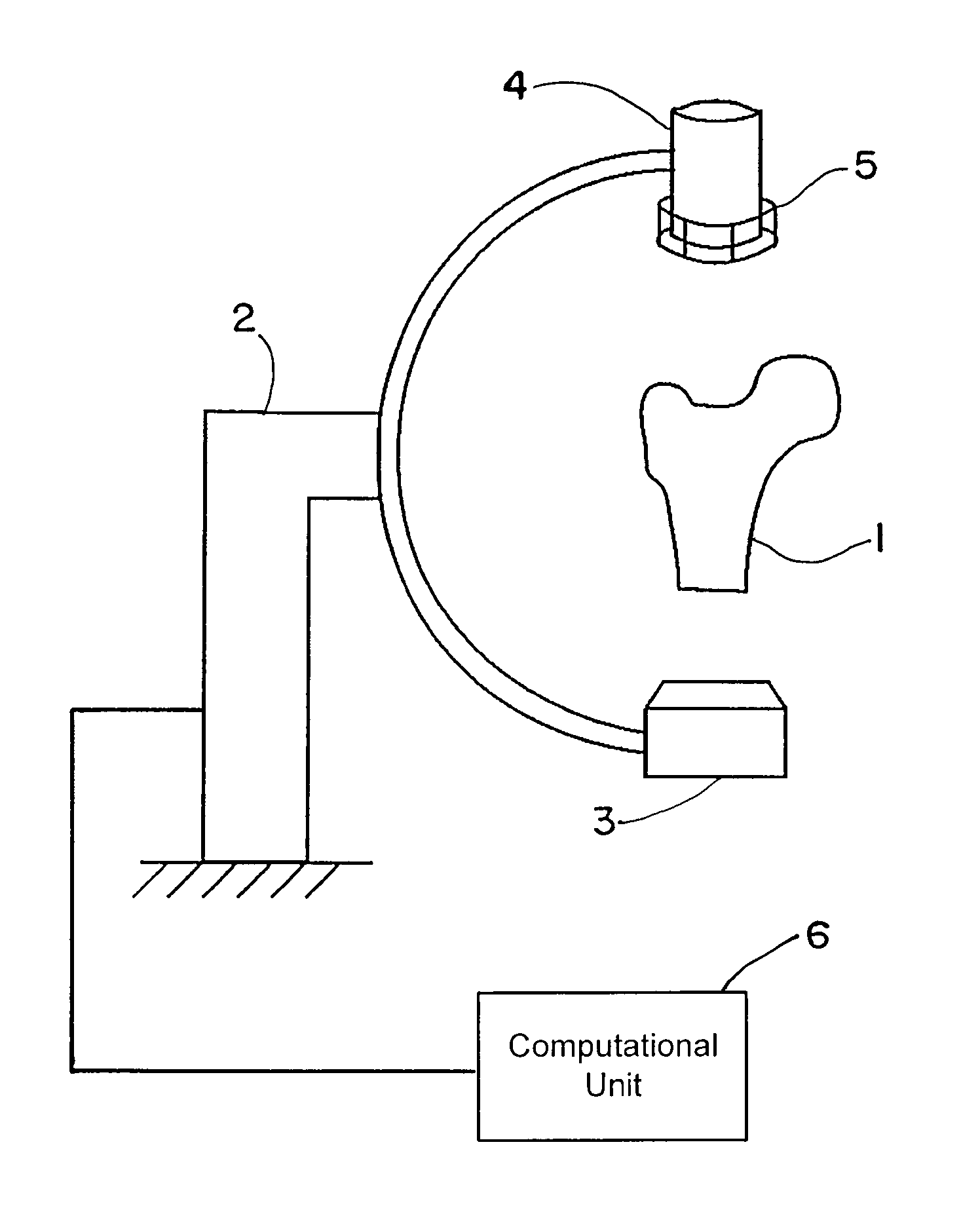
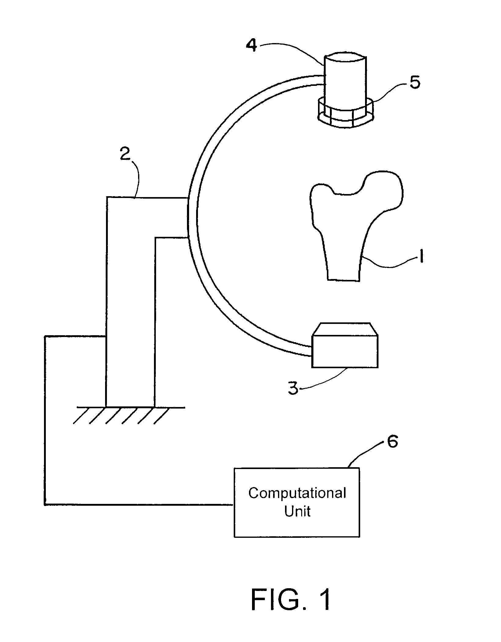
[0069]FIG. 1 shows an exemplary C-arc apparatus that can be used to obtain patient-specific X-ray images. An anatomic structure of interest, e.g., the proximal femur 1 of the patient, can be placed in the imaging unit 2. This imaging unit 2 may include a radiation source 3 and a detection device 4. A calibration device 5 connected to the detection device 4 can be used to determine the imaging parameters. The calibration device 5 may be placed anywhere between the radiation source 3 and the detection device 4, and attachment to the detection device is merely exemplary. Operatively coupled to the C-arc apparatus is a computational unit 6 that executes the algorithm described herein.

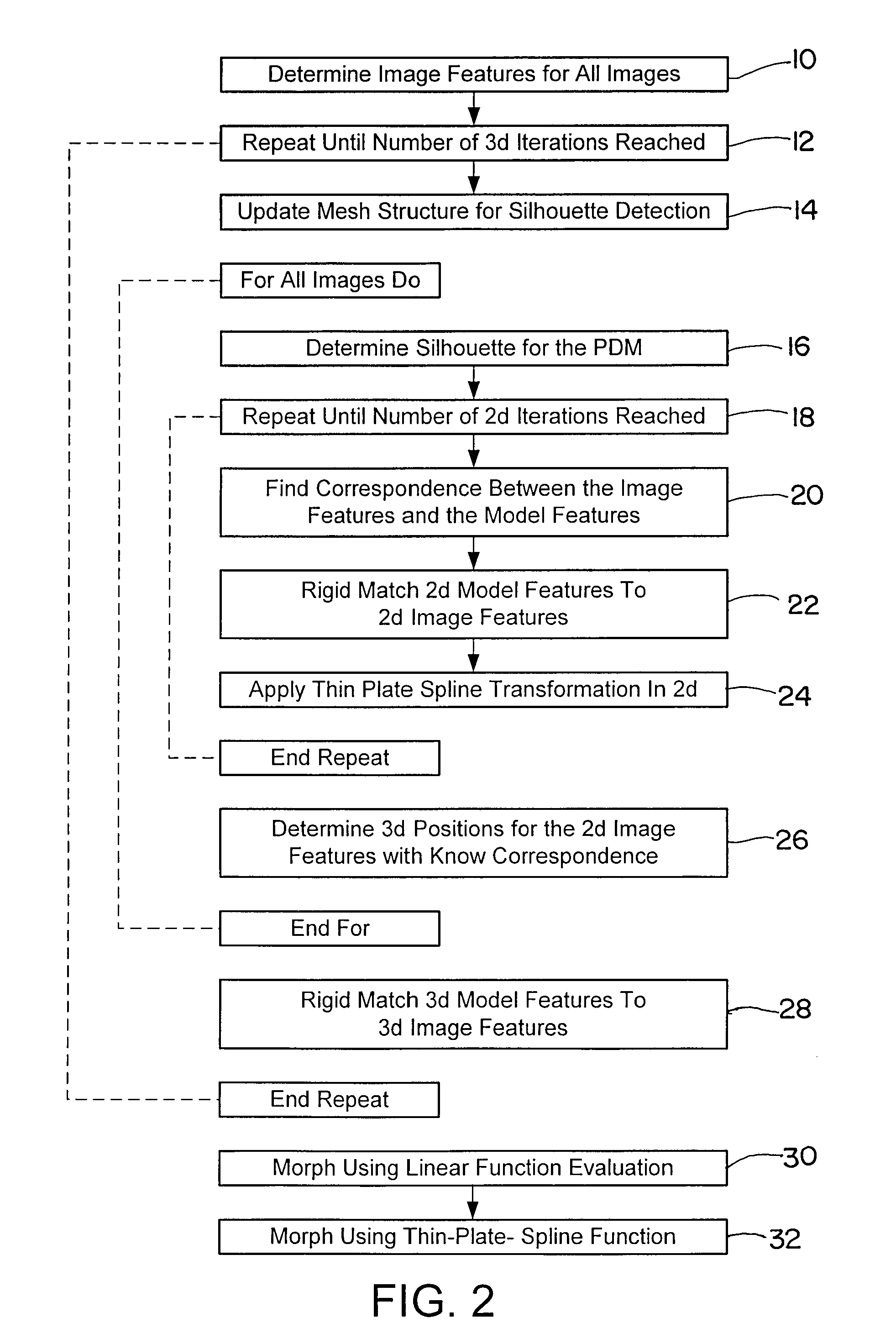
[0070]The image(s) obtained from the imaging device 2 can be used as input for the algorithm of FIG. 2 and executed by the computational unit 6. Beginning at block 10, image figures such as the shape, contour, outline or edge or gradients may be determined for all obtained two-dimensional images. At block 1...


PUM


Abstract

A method for generating a three-dimensional model of a structure based on at least one two-dimensional image of the structure includes obtaining a general three-dimensional model of the structure; determining at least one image feature from the at least one two-dimensional image; determining an orientation of the general three-dimensional model of the structure relative to the at least one two-dimensional image of the structure so that at least one image feature of a two-dimensional projection of the three-dimensional model match or at least approximate the at least one two-dimensional image feature; and after determining the orientation of the general three-dimensional model, morphing a form or shape of the general three-dimensional model to fit the at least one two-dimensional image.

Description

RELATED APPLICATION DATA[0001]This application claims priority of U.S. Provisional Application No. 60 / 826,786 filed on Sep. 25, 2006, which is incorporated herein by reference in its entirety.FIELD OF THE INVENTION[0002]The present invention relates generally to medical imaging, and more particularly to a method and apparatus for generating a three-dimensional (3D) model based on at least one two-dimensional (2D) image, such as the construction of a patient-specific three-dimensional model of a bone surface from one or more two-dimensional calibrated fluoroscopic images.BACKGROUND OF THE INVENTION[0003]Computer-assisted stereotactic systems that work with the aid of body structure data obtained from tomographic detection systems and with the assistance of X-ray images produced in situ are known, for example, from U.S. Pat. No. 4,791,934 and U.S. Pat. No. 5,799,055. Furthermore, x-ray imaging used to assist in operations is discussed in U.S. Pat. Nos. 5,967,982; 5,772,594; and 5,784,...

Claims


Application Information

Patent Timeline
Patent Type & Authority Patents(United States)
IPC IPC(8): G06T17/00
CPCG06T7/0051G06T7/50
Inventor FEILKAS, THOMASZHENG, GUOYAN
Owner BRAINLAB
Why Eureka
Try Eureka